1594
A dedicated coil for cerebellar fMRI1Spinoza Center, Amsterdam, Netherlands, 2King’s College London, London, United Kingdom, 3University Medical Center Utrecht, Utrecht, Netherlands
Synopsis
The function of human cerebellum is underexplored in vivo, due to its small size and its placement at the bottom of the brain where transmit fields are suboptimal at 7Tesla. Here, we combined 2 dense coil arrays of 16 small surface receive elements each with a transmit array of 3 antennas elements. Our results show improved B1+ and SNR close to the surface as well as g-factor gains compared to a whole-head commercial coil. This resulted in large gains in the surface (< 3.5cm) in the spatial extent of the BOLD activation, at the cost of increased signal inhomogeneity.
Introduction
The human cerebellum is involved in a wide-array of functions, ranging from motor control to executive functions and, as such, is of big neuroscientific interest1. However, its function is underexplored in vivo, due to its small size and dense structure, that necessitates high-resolution, and its placement at the bottom of the brain where transmit fields are suboptimal at 7Tesla2. This can be mitigated by optimizing the shape and number count of the transmit array for the region of interest3. Furthermore, high-resolution fMRI can be reached through increased SNR and improved parallel imaging4. Both of these can be achieved with high-density arrays of small receives that maximize the number of independent coil elements per unit distance and tend to show high SNR, since the noise deep into the tissue does not contribute to the signal picked up by the receiver4. In this study, we combined 2 dense coil arrays of 16 small surface receive elements each with a transmit array of 3 antennas elements to improve BOLD sensitivity in the human cerebellum at 7Tesla.Methods
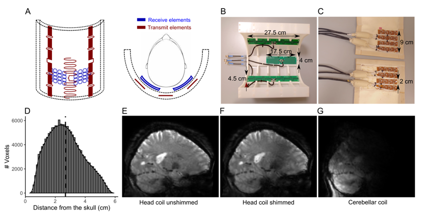
A 3-channel transmit and a 32-channel receive surface coil were developed by MR Coils. The design of the transmit antenna was optimized to fit in half-cylinder and to maximize B1+ at the back of the head. 3 antennas were used: 2 outer fractionated dipole antennas (27.5x4.5cm2) and a middle snake antenna (17.5x4cm2). The receive-coil consisted of 2 flexible arrays (8x10cm2) of 4 sets of 4 coils (2x3cm2 each) that were pressed against the back of the head. The coils partially overlapped to decouple adjacent elements. Six healthy volunteers were scanned twice in a Philips Achieva 7T, with a commercially available 8Tx/32Rx whole-head coil (Nova Medical) and the cerebellar coil (3Tx/32Rx). During the head coil session, data were acquired with and without B1 shimming. For each coil and B1-shim, a DREAM B1+ map was acquired (FOV=224x224x168mm3, voxel-size=3.5mm3, TR/TE=6ms/3ms, flip-angle=7o)5. The participants also performed a finger-tapping task (13s ON/13s OFF), while a BOLD-weighted 3D-EPI was acquired (FOV = 200x200x176mm3, voxel-size=1.8mm isotropic, TRvolume/TR/TE=1300ms/44 ms/17ms, flip-angle=13o, SENSEy/z=2.6/3.2). 5 reversed phase-encoding 3D-EPI volumes and an MPRAGE (FOV=200x221x180mm3, voxel-size=0.9mm isotropic, TR/TE=150ms/3ms, flip-angle=7o, SENSEy/z=2/2.5, TI1=1300ms) were also acquired for fieldmaps and anatomical reference. For one participant, a 3D-EPI with gradients and RF pulses turned and a 2D-EPI with increasing undersampling in Left-Right (2x1, 3x1, 4x1 and 6x1) were acquired, to allow SNR and g-factor estimates.The BOLD fMRI data were motion and distortion corrected, a GLM (finger-tapping>rest) was fitted (FSL 6.0.1) and 6 degrees-of-freedom EPI-to-MPRAGE and a diffeomorphic MPRAGE-to-MNI transform were calculated (ANTs 2.1). Z-stat, g-factor, SNR and B1-maps were projected to MNI and the Euclidean distance of each voxel towards the skull was calculated.Results
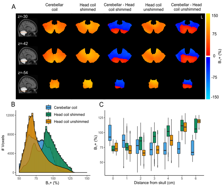
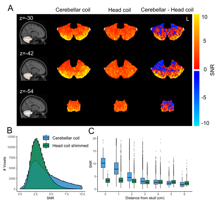
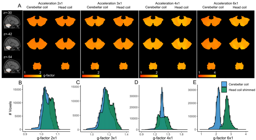
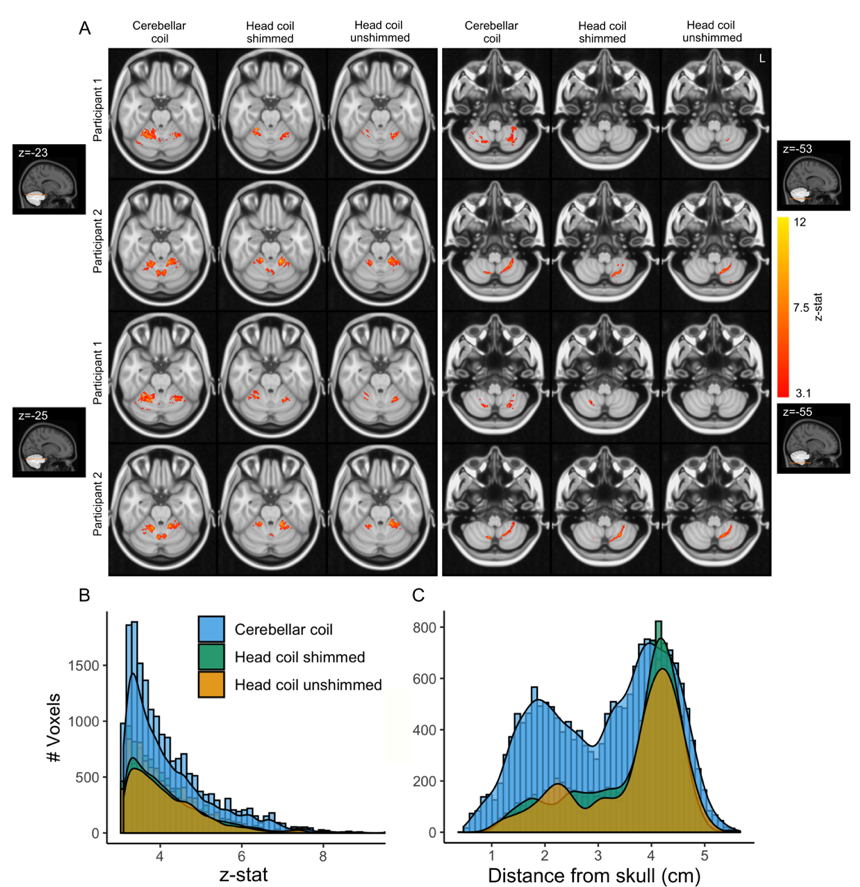
Within the cerebellum, the B1+ variation was similar for the cerebellar coil compared to the head coil following shimming (Figure 2B), with the cerebellar coil performing particularly well close to the surface (up to 3cm deep), where the head coil’s transmit field suffers the most. The SNR over the whole cerebellum was 27.5% higher and up to 308% higher close to the surface for the cerebellar coil (Figure 3B-C). Even up to RLR=6, the G-factor of the cerebellar coil was approximately 2, a large gain compared to the head coil (Figure 4B-E). As a result, more active voxels for the cerebellar coil were found, particularly close to the surface and at the bottom of the brain (Figure 5B-C).Discussion
In this study we demonstrated that a relatively simple array of small receive elements combined with a dedicated transmit array can markedly enhance BOLD imaging in the cerebellum compared to a whole-head coil.Surface coils are widely known to show high sensitivity close to the surface and to afford good parallel imaging performance4,6,7. Therefore, they have been used to improve fMRI in the visual cortex4. Here, high parallel-imaging performance (up to RLR=6) and high SNR up to 6cm from the surface were achieved. Our dedicated back-of-the-head transmit achieved high B1+ up to 3cm deep in the cerebellum compared to the head coil, but the B1+ uniformity did not improve.
Overall, the SNR and parallel imaging advantages of the cerebellar coil led to increased BOLD sensitivity in most of the cerebellum (up to 3-3.5cm deep, with the median distance of the cerebellum to the skull being 2.58cm; Figure 5). Optimization of the transmit phases of the head coil did not bring the same improvements. Our 2 receiver arrays, when placed in parallel, easily covered the required FOV for cerebellar imaging. The half-cylinder cerebellar coil may also be more comfortable and frees up valuable space for additional equipment.
Conclusion
fMRI research in critical brain regions like the cerebellum has so far been hindered by low SNR and spatial resolution. The cerebellar coil, consisting of 32 small surface coils arranged in 2 dense, high-count arrays and 3 back-of-the-head transmit elements, achieved improved BOLD imaging of the human cerebellum, compared to a commercial head coil with 8 transmit and 32 receive channels. The stronger BOLD signal we achieved will facilitate future research in the human cerebellum.Acknowledgements
No acknowledgement found.References
1. Stoodley CJ, Schmahmann JD. Functional topography of the human cerebellum. Handbook of clinical neurology. 2018;154:59-70.
2. Vaidya MV, Lazar M, Deniz CM, et al. Improved detection of fMRI activation in the cerebellum at 7T with dielectric pads extending the imaging region of a commercial head coil. J Magn Reson Imaging. 2018;48(2):431-440.
3. Sengupta S, Roebroeck A, Kemper VG, et al. A Specialized Multi-Transmit Head Coil for High Resolution fMRI of the Human Visual Cortex at 7T. PloS one. 2016;11(12):e0165418.
4. Petridou N, Italiaander M, van de Bank BL, Siero JCW, Luijten PR, Klomp DWJ. Pushing the limits of high-resolution functional MRI using a simple high-density multi-element coil design. Nmr in Biomedicine. 2013;26(1):65-73.
5. Nehrke K, Bornert P. DREAM--a novel approach for robust, ultrafast, multislice B(1) mapping. Magn Reson Med. 2012;68(5):1517-1526.
6. Hendriks AD, Luijten PR, Klomp DWJ, Petridou N. Potential acceleration performance of a 256-channel whole-brain receive array at 7 T. Magnetic Resonance in Medicine. 2019;81(3):1659-1670.
7. Fracasso A, Luijten PR, Dumoulin SO, Petridou N. Laminar imaging of positive and negative BOLD in human visual cortex at 7T. Neuroimage. 2018;164:100-111.
Figures