1592
A Continuously Adjustable 32-Ch Head Coil Array for MRI at 3T1MR Research, Department of Psychiatry, NYSPI and Columbia University, New York, NY, United States, 2Department of Electrical Engineering, New York University, New York, NY, United States, 3ZMBBI, Columbia University, New York, NY, United States
Synopsis
Close fitting is extremely crucial for RF coil arrays in order to maximize sensitivity. It is impossible to closely fit for all subjects of various head sizes using rigid head coil arrays. We presented a novel design of partially flexible 32-channel coil array to address the issue. The inner dimensions of the coil array can be smoothly adjusted from 180mmx220mm to 220mmx 260 mm, which fit for almost all head sizes of adult human subjects. The experiment results showed high imaging quality within the adjustable ranges. The coil array is highly practical for both research and clinical settings.
Introduction
As RF signals attenuate with distance rapidly, minimizing the distance between coil elements and subjects have received tremendous attentions[1-5] and many flexible chest and extremity RF coil arrays to closely fit for various shapes and sizes of subjects have been developed, for example, glove-like hand coil array [5]. However, for head imaging, a proper distance between subject’s head and the inner wall of coil arrays must be maintained due to the requirement of comfort for subjects. Completely flexible RF coil arrays touching head skin are, therefore, impractical for head scans. Consequently, head coil arrays remain rigid and are difficult to continuously adjust the distance and filling factors for different subjects of various head sizes. To address this issue, we presented a novel partially flexible 32-ch receive-only coil array.Material and Methods
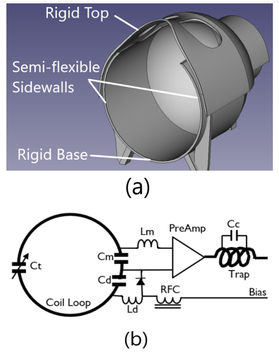
Our coil former was specially designed for continuous size-adjustment. It consists of two detachable parts: the lower part has a rigid base for support and semi-flexible sidewalls for adjustment; the upper part is rigid with two cuts for eye view (Figure 1a). The former was 3D-printed using two types of filaments: rigid PLA for base and top and semi-flexible TPU for side walls. The 3D printing was paused to change filaments at the joint of the base and sidewalls and quickly resumed so that the two types of materials were able to be bound together firmly. The upper part and lower part are attached by strong Velcro bindings and detachable for adjustment. In regular setting, the former has inner dimensions of 190mm x 240mm in horizontal and vertical directions respectively. However, when the upper part is lifted, its rigid widened edges will pull the flexible sidewalls of the lower part outwards, extending both the inner height and width of the coil array. The inner dimensions can be continuously adjusted from 180mm x 220mm to 220mm x 260mm, which fits for almost all human subjects, offering great potentials for optimizing filling factors for various head sizes while maintaining desirable comfort and safety.The coil elements were 12 AWG enameled copper wire loops in diameters of 1000mm for the two loops placed at view cuts and 700-800mm for other loops. The loops were laid out in three rings along inferior-superior direction with 10, 11, and 11 loops in each ring respectively. The wire segments of every individual coil element were connected by three capacitors. Each loop element was overlapped with adjacent elements for preliminary decoupling and then connected to an ultra-low-input-impedance (<=0.5 ohms) preamplifier for secondary decoupling. Each loop element was detuned with a LC trap circuit connected with a PIN diode driven by bias pulse from the MRI scanner during RF transmission (Figure 1b).
Results and Discussion
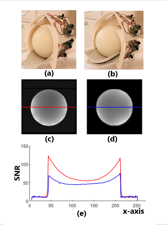
We acquired images from a sphere agar phantom having a diameter of 180 mm in a 3T MRI scanner (GE Premier) using a T1 anatomical pulse sequence (TR=8.4ms, TE=3.9ms, Flip Angle=14, FOV=256mmx256mm, Slice Thickness=2mm, TI=450ms, NEX=1, BW=41.67kHz, Matrix=256x256). To compare the performances of the coil array configured in different dimensions, we first acquired images with the coil set to 180mm x 220mm (Figure 2a), we then adjusted the coil former to 220mm x 260mm and repeated the acquisition (Figure 2b). The results show that images from both settings are of high SNRs and smoothness (Figure 2c and 2d). The setting of 180mm x 230mm, however, shows about 90% and 30% higher SNRs in periphery and center respectively than the setting of 220mm x 260mm, indicating closer fitting gained higher sensitivity (Figure 2e). Moreover, in the setting of 180mm x 220mm, periphery image has much higher SNRs than the center image. This is because the phantom was touching the bottom wall and sidewalls of the coil and the suffice of the phantom are, therefore, at the highest sensitivity region of the coil. In the setting of 220mm x 260 mm, the phantom was 20mm apart from the sidewalls and bottom walls of the coil. Thus, the sensitivity of the coil was more homogeneous inside the phantom and the image was more uniform. At the upper part, both images show lower SNRs because, for a sphere phantom, that part was more distant from the top wall of the coil in both settings. However, this will be significantly mitigated in human scans while human heads are mostly elliptical and closer to the top wall of the coil array.In addition, adjacent coil loops usually must be overlapped by a critical distance (about 22% of the loop diameter) in order to achieve desirable decoupling. In our case, the overlaps at the attaching part of the lower and upper coil former failed to meet this requirement during adjustment. However, the high and smooth SNR distributions demonstrated that the decoupling using ultra-low-impedance preamplifier worked well for continuous adjustment within the range of 180mm x 220mm to 220mm x 260mm.
Conclusions
Our 32-ch semi-flexible coil design is continuously adjustable and desirable for close-fitting for all adult head sizes. Of course, this is still in prototype and we are working on improving the design and finalizing the packaging. Especially, we will conduct experiments on human subjects of various head sizes when the risks of COVID-19 become lower.Acknowledgements
No acknowledgement found.References
1. Roemer PB, Edelstein WA, Hayes CE, Souza SP, Mueller OM. The NMR phased array. Magn Reson Med. 16:192-25(1990).
2. Reza Farivar, et al, Dense, Shape-Optimized Posterior 32-Channel Coil for Submillimeter Functional Imaging of Visual Cortex at 3T, Magn Reson Med. 76:321–328 (2016)
3. Kamil Uğurbil, et al, Brain imaging with improved acceleration and SNR at 7 Tesla obtained with 64‐channel receive array, Magn Reson Med. 82:495–509 (2019)
4. Joseph R. Corea, et al, Screen-printed flexible MRI receive coils, Nature Communications, Volume 7, id. 10839 (2016).
5. Bei
Zhang, Et al, A high-impedance detector-array glove for magnetic resonance
imaging of the hand, Nature Biomedical Engineering 2: 570–577(2018)
Figures