1589
A 2D High-Pass Ladder RF Coil Architecture for UHF MRI1Radiology, Weill Cornell Medicine, New York, NY, United States, 2General Electric Healthcare, Aurora, OH, United States, 3General Electric Healthcare Technologies, Waukesha, WI, United States
Synopsis
We propose a two-dimensional cylindrical high-pass ladder (2D c-HPL) volume coil architecture as a new class of radiofrequency coils to be used for 7T Body MR imaging. As a first simplified experimental proof-of-concept we show feasibility in a head sized coil. In silico results show 45% more homogeneous B1 field distribution with 25% lower specific absorption rate compared to a similar size birdcage coil. Experimental results are in good agreement with theory and numerical simulations. The proposed architecture shows promise to solve the longstanding open challenge of volume coil B1+ inhomogeneity in UHF MRI applications.
Introduction
Ultra-high-field (UHF) magnetic resonance imaging (MRI) (7T and above) promises improved signal-to-noise-ratio (SNR) [1-3]. However it comes with the critical barriers of higher specific-absorption-rate (SAR) and lowered transmit field (B1+) homogeneity, thereby holding back 7T-MRI from its full potential in the clinic [4-6].The ideal current patterns to reach ultimate intrinsic SNR at UHF are complex distributions that require novel RF coil concepts [7, 8]. Inductively coupled loop arrays exhibit high pass characteristics and can be used as MRI coils[9]. In order to improve intrinsic B1+ homogeneity over the length of the coil, we propose to use a two-dimensional high-pass ladder architecture in cylindrical form (2D c-HPL), which adds a second dimension in longitudinal direction to the well-established 1D MRI birdcage coil concept. Additionally, the proposed architecture uses inductively coupled loops, as opposed to electrically connected conductors, to address high SAR problem [10-13]. The concept proposed here is intended to be built as a volume body-sized coil; here we provide experimental feasibility in a head sized prototype [14,15].
Theory
The proposed c-HPL coil uses loop elements in the strong negative coupling, resulting in a dispersion relation $$\omega(\Omega,\Gamma)=\frac{1}{\sqrt{LC(1-2\kappa(cos\frac{\pi\Omega}{M+1}+cos\frac{2\pi\Gamma}{N})-4\kappa_d(cos\frac{\pi\Omega}{M+1}cos\frac{2\pi\Gamma}{N}))}}$$Here, Ω and Γ correspond to the mode numbers, M and N are the number of elements in z and transverse directions, respectively. κ and κd are the mutual coupling coefficients between neighboring and diagonal elements, respectively. L and C are the effective inductance and effective capacitance of a single element. This is a high-pass characteristics with an additional dimension, Ω.
Methods
We used an FDTD solver [16] to design a 7T 32-element 2D c-HPL coil prototype composed of four rows, where each row contains eight symmetrically placed elements. Each element has a length of 60 mm and 85 mm in z and transverse directions, respectively, a metallization width of 8 mm, and a separation of 5 mm in both directions. It is tuned to 298 MHz with four capacitors of 10 pF in the four respective corners.We drove the coil using 16 ports (i.e., 4 ports per row) in silico. We compared this design in simulation to a 16-leg high-pass birdcage coil tuned to 298 MHz (Figure 1a) with the same coil dimensions (diameter/length=23/25.5 cm). Both coils were loaded with a spherical phantom of 170 mm in diameter (εr=78 σ=0.46 S/m). The SAR, averaged over 1 g and 10 g of mass, was calculated [17]. The mean absolute deviation (MAD) from normalized B1+ distribution was calculated for a diameter of spherical volume (DSV) of 170 mm to compare B1+ non-uniformities.
The c-HPL head coil was manufactured using copper tape on a cylindrical former. The intended use for the coil is for it to be driven using the GE MR950 8-channel system from eight feed ports. The 16-channel mode analyzed in silico above can be realized using power splitters. For simplicity in this proof-of concept design, two active elements were used to drive the coil in quadrature mode (as opposed to the intended final use in 8-channel mode). Active elements were matched to 50 Ω at 298 MHz by using two trimmer capacitors in L-matching topology (1-23 pF, Voltronics) and a lattice balun composed of 28 nH inductors and 10 pF capacitors (Knowles Syfer). An in vitro image was obtained using a gradient echo sequence (TE/TR=1.5/5.1 ms, slice thickness=5 mm, matrix=256x128, FoV=210x210 mm, NEX=1) and a cylindrical phantom.
Results
We observed 32 resonance modes as suggested by theory (4 and 8 modes in the longitudinal and circumferential directions, respectively). Mode (1,1) (Figure 2) has the most homogeneous distribution and is suitable for imaging [9]. A selection of the additional modes inherent to the proposed 2D c-HPL configuration are provided in Figure-2.Figure-3 shows the manufactured coil and its return loss for the loaded case. Mode (1,1) is tuned to the imaging frequency and matched to the 50 Ω reference impedance.
Figure-4 shows the simulated B1+ distribution of the coil and the acquired image when using the c-HPL coil in quadrature mode, showing good agreement. B1+ intensity of approximately 0.7 $$$ \mu T/\sqrt{1W}$$$ was observed, which is sufficient for most MR imaging sequences. Experimental results also confirmed the numerically predicted B1+ falloff seen in the lower right portion of the coil, which stems from the fact that the coil circumference is comparable to the wavelength at 7T. This falloff appears when the coil is driven from only two ports around the circumference and will be mitigated in the final intended 8- or 16-channel feeding scheme.
Table 1 compares the B1+ uniformity and SAR results acquired from the simulations of c-HPL and birdcage coils with an RF power normalized to 1W. SAR and B1+ non-uniformity are approximately 25% and 45% lower than the birdcage coil, respectively.
Conclusion
A new RF coil architecture promising functionality as a 7T volume body coil [14,15] was proposed. The proposed 2D c-HPL coil exhibits 25% lower SAR and 45% better B1+ uniformity compared to birdcage geometry and was tested in a first in-vitro imaging experiment. Beyond these intrinsic advantages, the 2D design also allows for long coil designs [15] as well as the flexibility to add or remove elements due to inductive connection.Acknowledgements
This work was supported in part by the National Institute of Health (NIH) through R00EB024341. The authors are also grateful to GE Healthcare for the equipment support.References
[1] A. G. Van Der Kolk, J. Hendrikse, J. J. M. Zwanenburg, F. Visser, and P. R. Luijten, "Clinical applications of 7T MRI in the brain," European Journal of Radiology, vol. 82, no. 5, pp. 708-718, 2013, doi: 10.1016/j.ejrad.2011.07.007.
[2] E. Springer et al., "Comparison of Routine Brain Imaging at 3 T and 7 T:," (in en), Investigative Radiology, vol. 51, no. 8, pp. 469-482, 08/2016 2016, doi: 10.1097/RLI.0000000000000256.
[3] E. F. McKiernan and J. T. O’Brien, "7T MRI for neurodegenerative dementias in vivo: a systematic review of the literature," J Neurol Neurosurg Psychiatry, vol. 88, no. 7, pp. 564-574, 2017.
[4] O. Kraff and H. H. Quick, "7T: Physics, safety, and potential clinical applications," (in en), Journal of Magnetic Resonance Imaging, vol. 46, no. 6, pp. 1573-1589, 2017 2017, doi: 10.1002/jmri.25723.
[5] T. M. Fiedler, M. E. Ladd, and A. K. Bitz, "SAR Simulations & Safety," (in en), NeuroImage, vol. 168, pp. 33-58, March 1, 2018 2018, doi: 10.1016/j.neuroimage.2017.03.035.
[6] A. Sadeghi‐Tarakameh et al., "In vivo human head MRI at 10.5T: A radiofrequency safety study and preliminary imaging results," Magnetic Resonance in Medicine, vol. 84, no. 1, pp. 484-496, 2020, doi: 10.1002/mrm.28093.
[7] R. Lattanzi and D. K. Sodickson, "Ideal current patterns yielding optimal signal-to-noise ratio and specific absorption rate in magnetic resonance imaging: computational methods and physical insights," (in eng), Magnetic Resonance in Medicine, vol. 68, no. 1, pp. 286-304, Jul 2012 2012, doi: 10.1002/mrm.23198.
[8] R. Lattanzi, G. C. Wiggins, B. Zhang, Q. Duan, R. Brown, and D. K. Sodickson, "Approaching ultimate intrinsic signal-to-noise ratio with loop and dipole antennas," (in en), Magnetic Resonance in Medicine, vol. 79, no. 3, pp. 1789-1803, 2018 2018, doi: 10.1002/mrm.26803.
[9] H. U. Voss and D. J. Ballon, "High-pass two-dimensional ladder network resonators for magnetic resonance imaging," IEEE Trans Biomed Eng, vol. 53, no. 12 Pt 2, pp. 2590-3, Dec 2006, doi: 10.1109/TBME.2006.880870.
[10] M. A. Erturk, A. J. Raaijmakers, G. Adriany, K. Ugurbil, and G. J. Metzger, "A 16-channel combined loop-dipole transceiver array for 7 Tesla body MRI," Magn Reson Med, vol. 77, no. 2, pp. 884-894, Feb 2017, doi: 10.1002/mrm.26153.
[11] N. I. Avdievich, G. Solomakha, L. Ruhm, K. Scheffler, and A. Henning, "Evaluation of short folded dipole antennas as receive elements of ultra‐high‐field human head array," Magnetic Resonance in Medicine, vol. 82, no. 2, pp. 811-824, 2019, doi: 10.1002/mrm.27754.
[12] N. I. Avdievich, G. Solomakha, L. Ruhm, J. Bause, K. Scheffler, and A. Henning, "Bent folded‐end dipole head array for ultrahigh‐field MRI turns “dielectric resonance” from an enemy to a friend," Magnetic Resonance in Medicine, vol. 84, no. 6, pp. 3453-3467, 2020, doi: 10.1002/mrm.28336.
[13] A. A. Hurshkainen et al., "A parametric study of radiative dipole body array coil for 7 Tesla MRI," (in en), Photonics and Nanostructures - Fundamentals and Applications, vol. 39, p. 100764, May 1, 2020 2020, doi: 10.1016/j.photonics.2019.100764.
[14] S. Gokyar, H. U. Voss, V. Taracila, F. Robb, D. J. Ballon, and S. A. Winkler, "A Comparative Study Highlighting a Novel UHF MRI Volume Body Coil Design," Conference abstract, 2020, Dec, 15, Submitted to ISMRM.
[15] S. Gokyar, H. U. Voss, V. Taracila, F. Robb, D. J. Ballon, and S. A. Winkler, "An Electrically Long Ultra-High Field MRI Volume Body Coil Design," 2020, Dec, 15 Submitted to ISMRM.
[16] IT'IS Foundation, Sim4Life ver. 6.0, Zurich, Switzerland, 2020. [Online]. Available: https://zmt.swiss/sim4life/
[17] IEC 60601-2-33. Medical Electrical Equipment – Part 2-33: Particular Requirements for the Basic Safety and Essential Performance of Magnetic Resonance Equipment for Medical Diagnosis, Edition 3.1, I. E. Commission, Geneva, 2013.
Figures
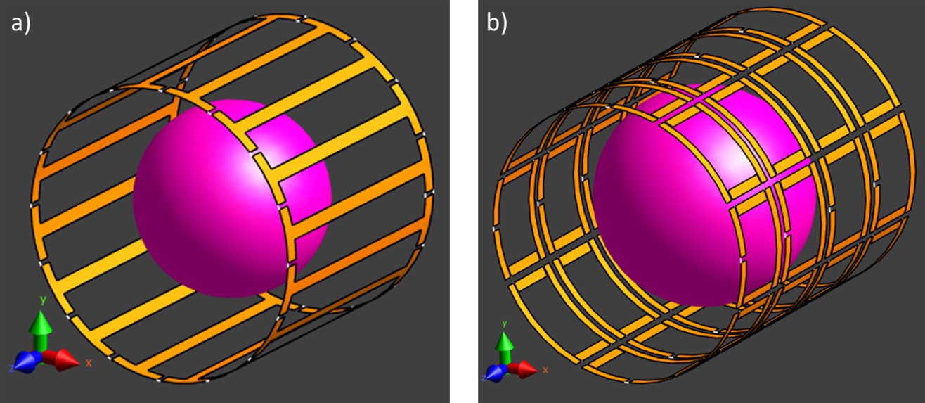
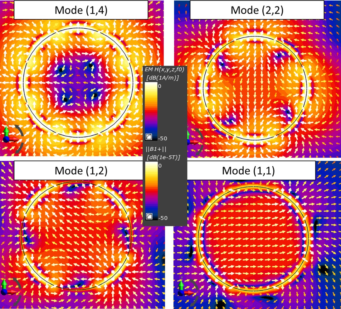
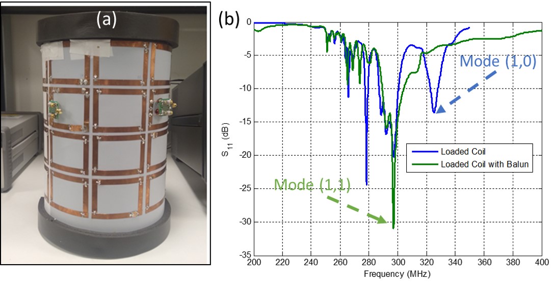
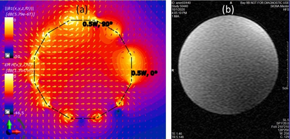
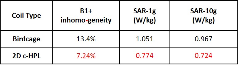
Table 1. B1+ homogeneity and SAR comparison of birdcage and 2D c-HPL coils for a diameter of spherical volume (DSV) of 17 cm. 2D c-HPL showed the best B1+ homogeneity, and SAR levels for 1 g and 10 g averaging for an accepted RF power of 1 W. The proposed architecture achieved an about 25% lower SAR, and 45% better B1+ inhomogeneity compared to the birdcage coil.