1588
Development of Microstrip Coils Integrated with High Dielectric Constant (HDC) Material to Improve B1 Field and Performance of 1H MR imaging at 7T1CMRR, Department of Radiology, University of Minnesota, Minneapolis, MN, United States, 2Biomedical Engineering, University of Minnesota, Minneapolis, MN, United States, 3CNMRR, Department of Neurosurgery, Penn State University, Hershey, PA, United States, 4Department of Engineering, Penn State University, Hershey, PA, United States
Synopsis
The development of ultra-high-field (UHF) magnetic resonance imaging (MRI) and spectroscopy imaging (MRSI) technologies improves sensitivity and spatial resolution for biomedical and clinical applications. However, the limited inherent signal-to-noise ratio (SNR) is still challenging, especially for pushing spatiotemporal resolution even at UHF. Previous studies have shown that high dielectric constant (HDC) materials could provide a new RF engineering solution for the challenge. In this study, we introduce a novel microstrip transmission line (MTL) transceiver array that uses HDC material as substrate, and significantly improves the RF transmission (B1+) and reception (B1-) fields and SNR for 1H imaging application at 7T.
Introduction
The demand for high-spatiotemporal resolution MRI/MRSI has promoted the rapid development of ultra-high-field (UHF) technologies. Current UHF human scanners can reach field strengths up to 11.4 T for providing high-quality human brain images1,2. However, the spatiotemporal resolution of MRI/MRSI is still limited by low intrinsic MR signals or signal-to-noise ratio (SNR) even at UHF. It has been proven that integrating high-dielectric-constant (HDC) materials with radiofrequency (RF) coils can significantly increase the RF transmission (B1+) and reception (B1-) magnetic fields, thereby improving SNR for MRI/MRSI applications3-5. Previous studies commonly placed HDC materials between the imaging object and the RF coil(s). This made it difficult to compare the B1 fields with and without HDC materials, since the coil should be placed close to the object without additional distance4-7. Herein, we report a newly designed microstrip transmission line (MTL) RF transceiver array8,9 that was built on a human-head helmet filled with HDC materials to largely improve the RF coil B1 fields and MRI performance at 7T.Methods
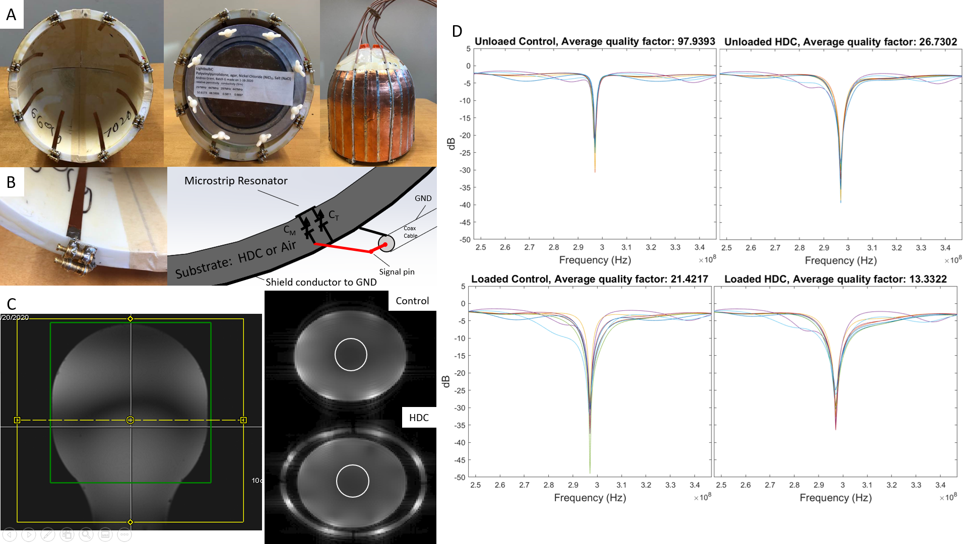
A head-shaped phantom (65% PVP, 1.7% NaCl, 0.04% NiCl·6H2O, 2% Agar) for mimicking human brain tissue properties was employed for benchtop testing and MR scanning at Siemens 7T/90cm human scanner. Two 4-piece helmet-shaped formers (PETG) were 3D-printed, which can tightly fit the phantom and most human heads, and filled with the HDC material (25% BaTiO3, εr=138) and air (εr=1, Control), respectively. Two physically identical 8-channel MTL transceiver arrays operating at 7T proton frequency (298 MHz) were built on the helmet-shaped formers (Fig. 1A&1B). The HDC material and air served as the substrates for the two MTL transceiver arrays, respectively. By measuring the scattering parameters under head-shaped phantom loaded and unloaded conditions, their tunability and couplings were evaluated. Actual flip-angle images (AFI) with circular-polarized (CP) and/or B1-shimmed modes were applied to estimate the B1 fields of the HDC and the control MTL transceiver arrays. Gradient echo (GRE) images with varied flip angle were collected, and methods developed by Van de Moortele et al.10,11 were applied to estimate the B1-shimmed phases, and relative transmission and reception fields in each coil array and/or condition. Thirty-six image slices (3-mm slice thickness) in the middle of the phantom were used to compare the average B1 fields of the HDC-MTL transceiver array to those of the Control.Results
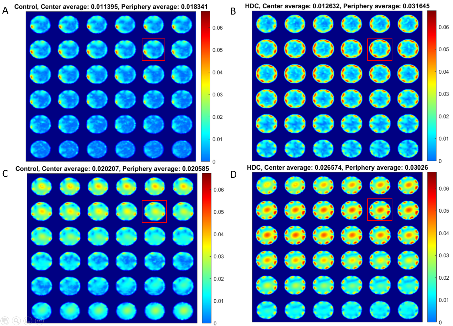
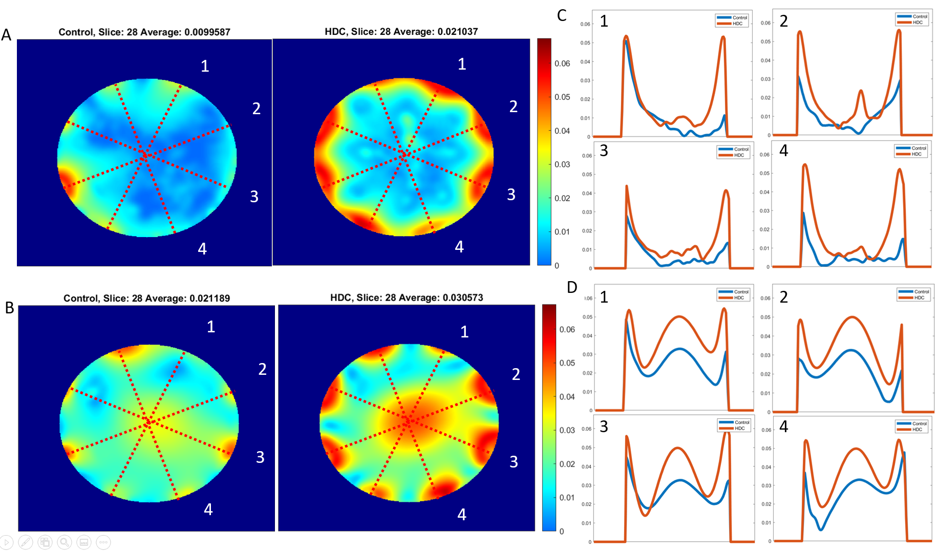
Fig. 1D shows that the quality factors of the control coil array were higher than those of the HDC coil array under unloaded and loaded conditions. This indicates that the HDC helmet enhanced the loading effect of the coils. The couplings among neighboring MTL channels in each array were below -14dB under loaded and unloaded conditions, indicating good decoupling among them. Fig. 1C illustrates the slice positions of GRE images and the regions of interest (ROI) selected to calculate B1-shimmed phases.Fig. 2 shows estimated B1+ fields of the imaging slices in the middle of the phantom for each case. The center slices of estimated B1+ maps and selected profiles are shown in Fig. 3 for detailed comparisons. They collectively indicate that the averaged B1+ field of the HDC-TML transceiver array was 2.1 and 1.4 times higher than that of the Control under the CP mode and B1-shimmed mode, respectively.
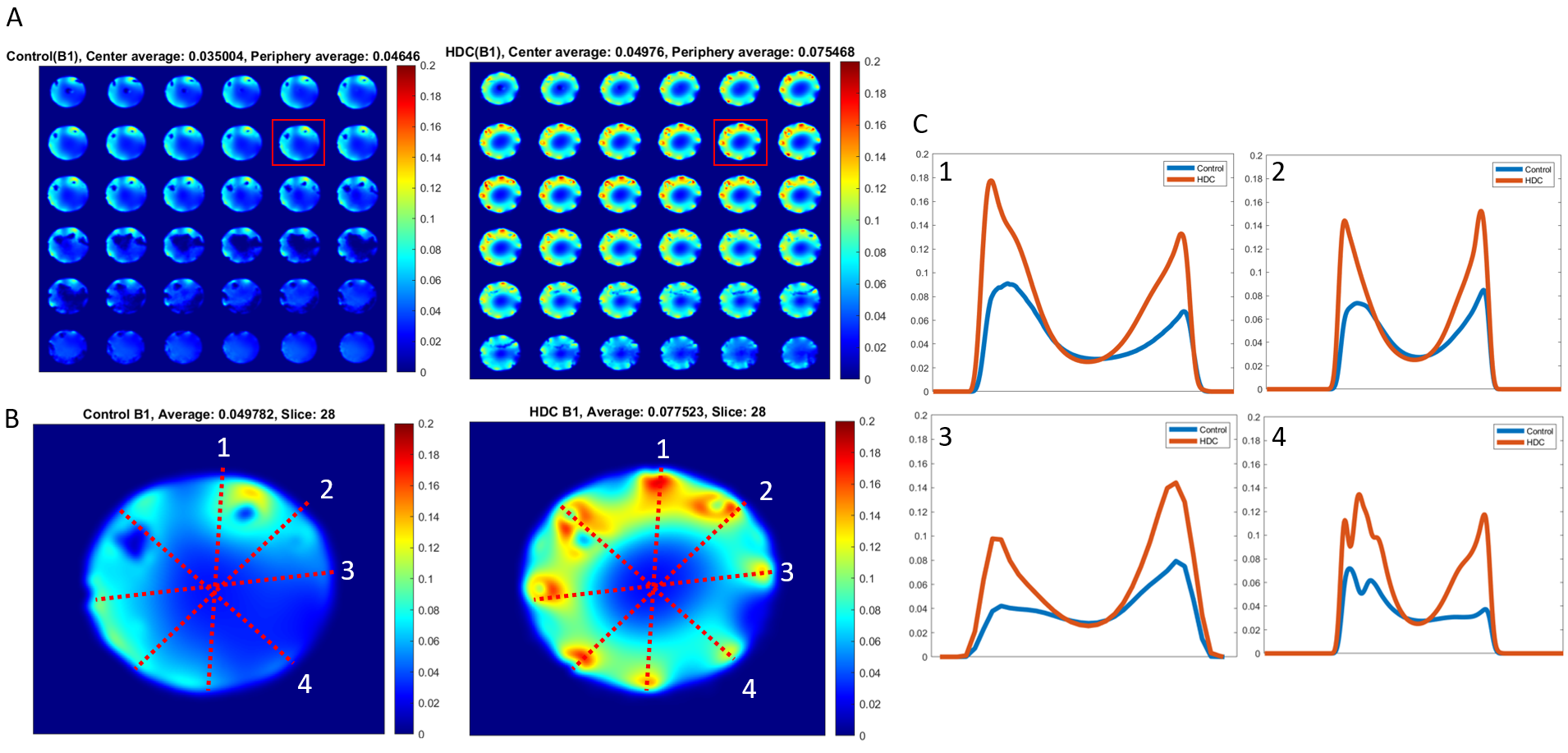
The averaged B1- fields (Fig. 4A) with the HDC-MTL transceiver array was 1.4 and 1.6 times higher than that of the Control in the central voxels and periphery voxels, respectively. The averaged B1- field of the center slice (Fig. 4B) with the HDC-MTL transceiver array was 1.6 times higher than that of the Control, which is also evident in the profile comparison shown in Fig. 4C.
Discussion
In this study, a novel integrated HDC-MTL transceiver array for human brain imaging at 7T implemented the HDC materials as the substrate for conventional MTL resonators. Unlike other RF coil designs operated with HDC materials, the HDC-MTL transceiver array maintains lossless SNR with a close distance between RF coils and imaging objects. Therefore, the compact coil design is one key merit of the HDC-TML transceiver array that can achieve large B1 improvements and sensitivity enhancement for proton imaging at UHF. The improvement of the HDC-MTL transceiver array in averaged B1+/- fields across space was highly significant, in particular, in the periphery regions (60-100%) though relatively less in the central regions (see Figs. 2-4). The SNR is proportional to B1- field strength; thus, the increased B1- field by the HDC-TML transceiver array can be translated into a large SNR gain. An interesting observation from examining Fig. 3B and Fig. 4B was the rotation of “hot” B1- zones in the periphery areas by approximately 22° as compared to the “hot” B1+ zones. This could be explained by the polarization of the B1 fields owing to RF wave behavior at UHF12.Conclusion
The newly designed HDC-TML transceiver array significantly largely improves the B1 fields and 1H MRI performance at 7T. Nevertheless, the findings of this study (for a proof of concept) were drawn from the sub-optimal condition and the coil design and performance can be further improved aiming for human brain 1H MRI/MRSI applications at UHF. The same coil concept can be applied to other magnetic field strengths or other nuclear spins.Acknowledgements
This work was supported in part by NIH grants of U01 EB026978, R01 CA240953, R24 MH106049, T32 EB008389, S10 RR026783, P41 EB027061, P30NS076408 and R21 EB009133.References
1. Ugurbil, K. (2012). The road to functional imaging and ultrahigh fields. Neuroimage, 62(2), 726-735. doi:10.1016/j.neuroimage.2012.01.134
2. Ladd, M. E., Bachert, P., Meyerspeer, M., Moser, E., Nagel, A. M., Norris, D. G., . . . Zaiss, M. (2018). Pros and cons of ultra-high-field MRI/MRS for human application. Prog Nucl Magn Reson Spectrosc, 109, 1-50. doi:10.1016/j.pnmrs.2018.06.001
3. Ladd, M. E., Bachert, P., Meyerspeer, M., Moser, E., Nagel, A. M., Norris, D. G., . . . Zaiss, M. (2018). Pros and cons of ultra-high-field MRI/MRS for human application. Prog Nucl Magn Reson Spectrosc, 109, 1-50. doi:10.1016/j.pnmrs.2018.06.001
4. Lee, B. Y., Zhu, X. H., Rupprecht, S., Lanagan, M. T., Yang, Q. X., & Chen, W. (2017). Large improvement of RF transmission efficiency and reception sensitivity for human in vivo(31)P MRS imaging using ultrahigh dielectric constant materials at 7T. Magn Reson Imaging, 42, 158-163. doi:10.1016/j.mri.2017.07.019
5. Rupprecht, S., Sica, C. T., Chen, W., Lanagan, M. T., & Yang, Q. X. (2018). Improvements of transmit efficiency and receive sensitivity with ultrahigh dielectric constant (uHDC) ceramics at 1.5 T and 3 T. Magn Reson Med, 79(5), 2842-2851. doi:10.1002/mrm.26943
6. Yang, Q. X., Mao, W., Wang, J., Smith, M. B., Lei, H., Zhang, X., . . . Chen, W. (2006). Manipulation of image intensity distribution at 7.0 T: passive RF shimming and focusing with dielectric materials. J Magn Reson Imaging, 24(1), 197-202. doi:10.1002/jmri.20603
7. Chen, W., Lee, B. Y., Zhu, X. H., Wiesner, H. M., Sarkarat, M., Gandji, N. P., . . . Lanagan, M. T. (2020). Tunable Ultrahigh Dielectric Constant (tuHDC) Ceramic Technique to Largely Improve RF Coil Efficiency and MR Imaging Performance. IEEE Trans Med Imaging, 39(10), 3187-3197. doi:10.1109/TMI.2020.2988834
8. Zhang, X., Ugurbil, K., & Chen, W. (2001). Microstrip RF surface coil design for extremely high-field MRI and spectroscopy. Magn Reson Med, 46(3), 443-450. doi:10.1002/mrm.1212 [pii]
9. Zhang, X. L., Ugurbil, K., & Chen, W. (2003). A microstrip transmission line volume coil for human head MR imaging at 4 T. Journal of Magnetic Resonance, 161(2), 242-251. doi:10.1016/S1090-7807(03)00004-1
10. Van de Moortele P., Urgurbil K. Very Fast Multi Channel B1 Calibration at High Field in the Small Flip Angle Regime. Proc Intl Soc Mag Reson Med 2009; 17: 367
11. Van de Moortele PF, Snyder C, DelaBarre L, Adriany G, Vaughan JT, Ugurbil K. Calibration tools for RF shim at very high field with multiple element RF coils: from ultra fast local relative phase to absolute magnitude B1+ mapping. Proc 15th Annual Meeting ISMRM; Berlin, Germany. 2007. p. 1676.
12. Wang J, Yang QX, Zhang X, Collins CM, Smith MB, Zhu XH, Adriany G, Ugurbil K and Chen W. (2002). Polarization of the RF field in a human head at high field: a study with a quadrature surface coil at 7.0 T. Magn Reson Med. 48:362-9.
Figures