1587
Circularly polarized coil for 1.5 T MRI RF harvesting1The Department of Physics and Engineering, ITMO University, Saint Petersburg, Russian Federation, 2Max Delbruck Center for Molecular Medicine in the Helmholtz Association, Berlin, Germany
Synopsis
The concept of the wireless power supply for the MRI coils demands high efficiency in a restricted volume. To meet these requirements, we investigated the possibility of harvesting the energy from the B1 field of a 1.5 T MRI scanner using a new volumetric coil design. We performed a series of experiments with the different positions of the proposed coil within the scanners bore and estimated the accepted power levels during the different types of MR pulse sequences.
Main findings
In this work, we demonstrate a new circularly polarized (CP) volumetric coil design for energy harvesting in a 1.5 T MRI scanner and evaluated its performance at various locations along the B0 field axis inside the bore and during the different MR pulse sequences.Introduction
One of the most common MRI systems available at clinics is 1.5 T scanners, which employ a large birdcage-type body coil for the transmit, creating a circularly polarized (CP) RF magnetic field. The need to use high power during nuclei excitation gives rise to the idea of taking some of this energy to feed wireless devices for patients' health monitoring or local coil amplifiers and detuning circuits1. However, this concept has two significant limitations inherent in MRI. First, the harvesting circuitry must be compact since the free space inside the scanner is strictly limited. Second, the presence of wireless devices should not disturb the imaging process. Numerous investigators implement small weakly coupled resonant single turn2,3 or multiturn4,5 loops located away from the imaging object to meet both requirements. This design limits the harvesting system's efficiency since such flat structures are working with the linearly polarized magnetic fields. We propose a new design of a compact volumetric harvesting coil that can work with circular polarization and receive the energy from two CP-polarized RF magnetic fields.Methods
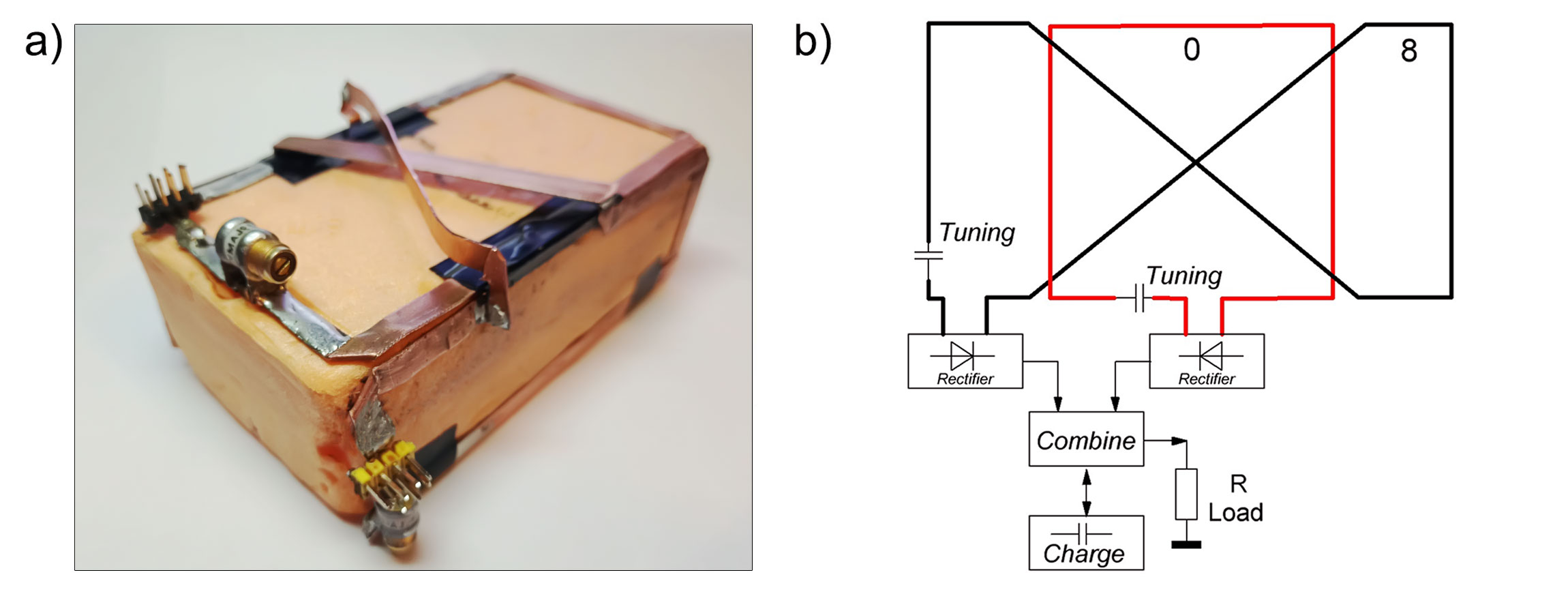
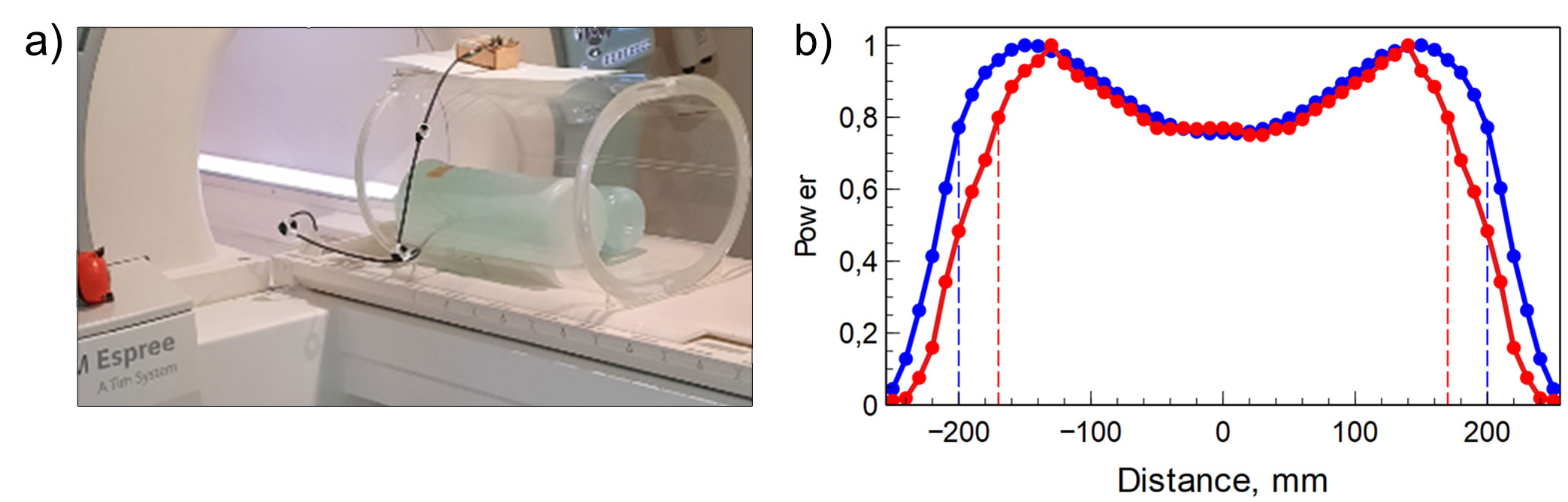
The harvesting coil prototype consists of two loops similar to the so-called "butterfly" design with flat 0-shaped and bent 8-shaped elements. These elements are assembled on polystyrene foam brick and occupy three of its edges with dimensions 110x62 mm for the top and 110x37 mm for the sides (Fig. 1a). Such design has the advantage of geometrically decoupling the coils while keeping the overall relatively small size. Each coil is connected to the low-impedance rectifier circuit based on VS-15MQ040-M3 Schottky diodes. The rectifiers' outputs are combined in series to increase the resulting DC voltage (Fig. 1b). The output voltage was measured using a 14-bit oscilloscope Owon XDS3202A, and the harvested power was calculated using this value. In perspective, the RF harvesting should provide power to the local coil circuitry during each phase encoding step, so we measured the power output with a single excitation pulse. For this, we used a manual frequency adjustment procedure. It employs three separate pulses, but we measured the harvesting output only during the first one. We perform several measurements to investigate the potential working region for the harvesting coil inside the MR scanner. The harvesting coil was located on top of a body phantom (Fig. 2a). It was moved with the patient table in the direction of the main static field to evaluate the harvesting power dependence on the coil positions. We have performed two sets of experiments on Siemens Avanto and Siemens Espree 1.5 T systems. Also, the harvested power was measured for various applied imaging sequences when the coil with the phantom was placed in the magnet's isocenter (Siemens Espree 1.5 T).Results
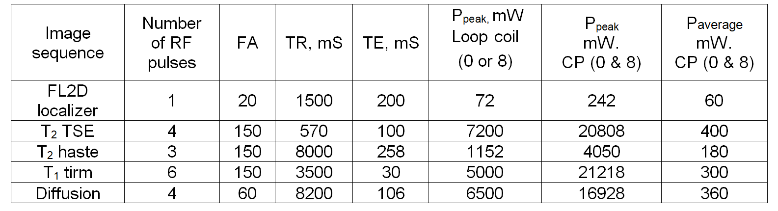
The body coil size varies from one MRI machine to another. The results of the experiments with the harvesting coil position are demonstrating this difference in Figure 2b. The potential area for the harvesting volumetric coil placement is limited by the region -180:180 mm for Siemens Espree and -200:200 mm for Siemens Avanto. In this region, the coil demonstrates its maximum performance when located on the top of the body phantom. The type of MR pulse sequence used also influences the amount of harvested energy. Since many parameters can be adjusted in each sequence, we have selected the most relevant ones for consideration in Figure 3. It was observed that the harvesting voltage for FL2D sequence was small because of the low power examination (low flip angle (FA)) and only one pulse used for excitation. But for some pulse sequences, such as the T2 TSE, harvesting worked better due to the high-power examination (high flip angle), many pulses in the excitation phase, and low TR.Discussion and Conclusion
The proposed CP harvesting coil improves RF harvesting efficiency by receiving CP RF magnetic field during the transmit. We have demonstrated that the proposed element's RF harvesting efficiency depends on the position within the body coil (and its dimensions) and the applied pulse sequence. The average duration of one B1 excitation pulse was about 100 us, which allows us to receive more 10W peak power with a 110x67x32 mm volume butterfly coil. However, the estimated average power at each step of the phase encoding cycle will be about 100-500 mW. It is possible to increase total harvested power by combining additional harvesting structures or by the increase of its size.Acknowledgements
This work was supported by the Russian Science Foundation (Project 19-75-10104).References
1. Nohava, L., Ginefri, J.C., Willoquet, G., Laistler, E., & Frass-Kriegl, R. (2020). Perspectives in Wireless Radio Frequency Coil Development for Magnetic Resonance Imaging Frontiers in Physics, 8, 11.
2. Kelly Byron, Fraser Robb, Shreyas Vasanawala, John Pauly, and Greig Scott. "Harvesting Power Wirelessly from MRI Scanners”, Proceedings of the 27th Annual Meeting of ISMRM, 2019.
3. J. H¨offlin et al., “Energy harvesting with a figure-8 coil - towards energy autonomous MRI detection,” in Proc. Exp. Nucl. Magn. Resonance Conf., 2016.
4. Höfflin, Jens, et al. "Energy Harvesting towards autonomous MRI detection." Proceedings of the 21th Annual Meeting of ISMRM, 2013.
5. Venkateswaran, Madhav, et al. "Wireless Power Harvesting During MRI." 2020 42nd Annual International Conference of the IEEE Engineering in Medicine & Biology Society (EMBC). IEEE, 2020.
Figures