1586
Quadrature Tx/Rx wireless coil for targeted breast MRI at 1.5 T1Department of Physics and Engineering, ITMO University, St. Petersburg, Russian Federation, 2Institut Langevin, ESPCI Paris, CNRS, PSL University, Paris, France, 3Research and Practical Clinical Center for Diagnostics and Telemedicine Technologies of the Moscow Health Care Department, Moscow, Russian Federation
Synopsis
We demonstrate for the first-time a quadrature transceive wireless coil for 1.5T targeted breast MRI. The proposed concept features two volumetric resonators: metamaterial-inspired structure and Helmholtz coil. These coils are electromagnetically coupled to the body birdcage coil and interact with its magnetic field’s components, thus boosting body coil transmit efficiency, SAR efficiency, and receive performance for the targeted area of the human breast.
Introduction
Wireless coils based on ceramic materials1,2 or metamaterial inspired structures3-5 recommended themselves as an excellent alternative to the cable-connected local receive-only and transceive (Tx/Rx) coils. The application of volumetric metamaterial-inspired coil (M-coil)5 for the targeted breast MRI at 1.5T was recently demonstrated. Such a coil via electromagnetic coupling with a body coil effectively focuses the magnetic flux in the breast area, substantially improving transmit and SAR efficiencies of a body transmit coil. However, this coil5 is linearly polarized (i.e., it interacts only with the y-component of the body coil’s magnetic field), meaning that about the square root of two of efficiency is lost. Here, we propose and demonstrate via numerical study a new design of a wireless coil, combining two volumetric resonators: M-coil structure and Helmholtz coil (H-coil) to create a quadrature RF magnetic field with a particular application to breast imaging at 1.5T.Methods
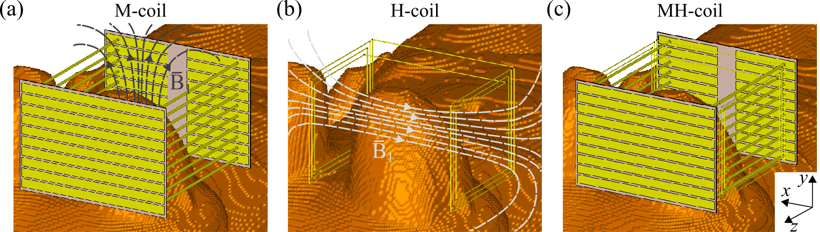
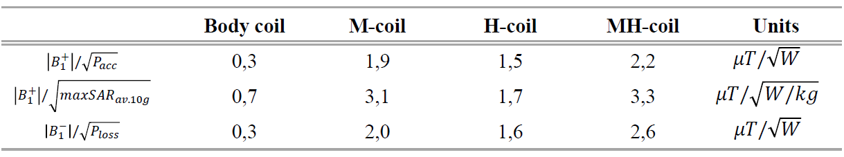
Figure 1a demonstrates the M-coil design. It consists of 10 split-loop resonators containing two parallel telescopic brass tubes connected by two structural capacitors at their ends. The capacitors are implemented as overlapping between the copper strips printed on the opposite sides of the dielectric substrate with ε=2.5, tan δ=0.0013 (Arlon 255C) with the following dimensions 164×114×1 mm3. The resonator dimensions were chosen based on the average size of the human breast. To tune the M-coil to the Larmor frequency of 1H 1.5Т MRI, the size of capacitive strips was optimized (9×69 mm2 – for internal strips, 9×160 mm2 – for the outer ones) as well as slight tuning of the wire length was performed (l=163 mm). This coil is excited by the y-component of the body coil’s magnetic field. Figure 1b shows an H-coil design consisting of three turns of copper wire forming three loops with the following dimensions: 124×105 mm2, 114×95 mm2, and 104×85 mm2. A distance of 150 mm separates two pairs of turns. H-coil also was tuned to the 63.68 MHz, keeping its dimensions suitable for breast imaging, and it interacts with the x-component of the body coil’s magnetic field. Figure 1c shows a quadrature coil based on the M-coil and H-coil combination, which can be easily located around the breast. All electromagnetic calculations were performed in CST Studio Suite 2020. The numerical model includes a shielded high-pass body birdcage coil with 16 legs, 350 mm inner diameter, and 650 mm length and a female voxel model based on Ella from the Virtual family6 modified by adding breast phantom No. 1 from the UWCEM Numerical Breast Phantom Repository7. We compared four setups: (1) a voxel model placed inside the body coil without the wireless coil; the same system with M-coil (2), H-coil (3), and MH-coil (4) placed around the breast. The calculated B1+ field and SAR (10g averaged) distributions were normalized to 1W of total accepted power by the body coil. The M-coil, H-coil, and MH-coil effect on the body coil receive performance was evaluated as $$$\small{|B_1^-|/\sqrt{P_{loss}}}$$$, where Ploss – power absorbed in the body.Results
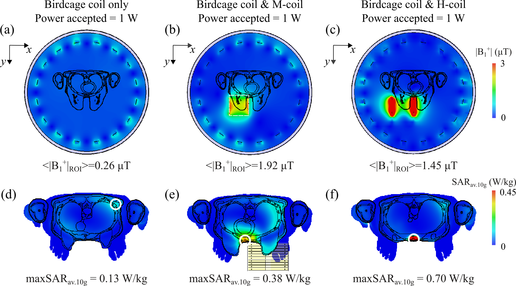
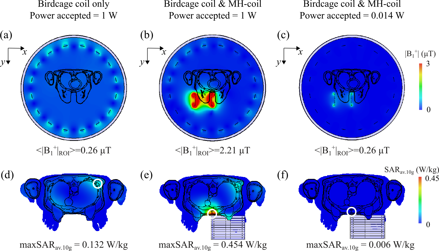
Figure 2 shows the B1+ field and SARav.10g maps for the setups (1)-(3). Strong localization of the B1+ field in the breast area with the M-coil led to a 7.4-fold enhancement in the breast area’s body coil’s transmit efficiency. Whereas adding the H-coil around the breast resulted in a 5.6-fold gain in the body coil’s transmit efficiency. The maximum of local SARav.10g for both wireless coils is observed in the abdominal muscles. The maximum local SARav.10g value for the H-coil is higher than that of the M-coil and equal to 0.70 W/kg and 0.38 W/kg, respectively. Figure 3 shows the distributions of the B1+ field and SARav.10g for body coil without (Figure 3a,d) and with (Figure 3b,e) quadrature MH-coil. We obtained an 8.4-fold enhancement in the body coil’s transmit efficiency thanks to the wireless MH-coil due to the simultaneous interaction with two magnetic field components. Thus, to obtain the same root mean square B1+ value for the MH-coil inside the breast area as for the body coil alone, one can reduce radiofrequency input power by 70.6 times (Figure 3c). That leads to a 22-fold decrease in the local SARav.10g maximum, compared to a body coil used alone (Figure 3f). The results for transmit efficiency, SAR efficiency ($$$\small{|B_1^+|/\sqrt{maxSAR_{av.10g}}}$$$), and receive performance are summarized in Table 1 for all considered cases.Discussion and conclusions
In this work, we demonstrated the quadrature Tx/Rx wireless coil, which can be efficiently applied for targeted breast imaging at 1.5T. Numerical calculations of the quadrature coil have shown a 15% increase in transmit efficiency for almost the same SAR efficiency and a 30% increase in receive performance compared to the linearly polarized M-coil (Table 1). However, Figure 3b demonstrates an increase in the inhomogeneity of the B1+ distribution across the breast area in comparison with a case of body coil used alone. This issue can be solved via the adjustment of the radiofrequency pulse shapes8. Further investigations, including practical implementation of the MH-coil, phantom, and in vivo imaging, and comparison with local cable-connected coils, are ongoing.Acknowledgements
This work was supported by the grant of the Russian Science Foundation (№ 18-75-10088).References
1. Shchelokova A et al. Ceramic resonators for targeted clinical magnetic resonance imaging of the breast. Nat. Commun. 2020;11:3840.
2. Ivanov V et al. Coupled very-high permittivity dielectric resonators for clinical MRI. Appl. Phys. Lett. 2020;117:103701.
3. Shchelokova A et al. Volumetric wireless coil based on periodically coupled split-loop resonators for clinical wrist imaging. Magn. Reson. Med. 2018;80(4):1726-1737.
4. Shchelokova A et al. Wireless coil as a portable and practical alternative to a dedicated transceive coil for extremities MRI at 1.5T. Proc. Intl. Soc. Mag. Reson. Med. 2019;27,0273.
5. Puchnin V et al. Metamaterial inspired wireless coil for clinical breast imaging J. Magn. Reson. 2021;322:106877.
6. A. Christ et al. The Virtual Family - development of surface-based anatomical models of two adults and two children for dosimetric simulations. Phys. Med. Biol. 2010;55:23-38
7. Burfeindt MJ et al. MRI-derived 3D-printed breast phantom for microwave breast imaging validation. IEEE Antennas Wirel. Propag. Lett. 2012;11:1610-1613.
8. van Kalleveen IML et al. Adiabatic turbo spin echo in human applications at 7 T. Magn. Reson. Med. 2012;68:580-587.
Figures