1585
High power RF amplifier for UHF MRI with configurable number of channels1Lauterbur Imaging Research Center, Shenzhen Institutes of Advanced Technology, Chinese Academy of Sciences, Shenzhen, China, 2United Imaging Healthcare, Shanghai, China
Synopsis
Increasing magnetic field strength can improve signal-to-noise ratio (SNR) of MRI [1] and it requires higher power capability and fidelity from RF Power Amplifier (RFPA). Meanwhile, to reduce B1 inhomogeneity at high field usually requires multi-channel parallel transmission (pTx) technique. In this study, we present a method to design RFPA with high power capability and output linearity, and with configurable number of transmit channels so as to meet different RF coil and load requirements.
Introduction
The main function of RFPA is to transmit high fidelity RF waveform with specific frequency, bandwidth, amplitude and phase. RFPA drives RF coil to generate circular or elliptically polarized B1 field in region of interest. Ultra-high field (UHF) MRI systems are usually equipped with 8 channels or more and each channel generates 1~2 kW peak power [2] which is enough for head imaging or local extremity imaging. For body imaging, higher power per channel is usually necessary if pTx is required. UHF MRI systems are often used with many different RF transmit coil array configurations for different imaging purposes. RFPA with fixed number of channels and power capability limit the use of different RF coil set-ups. This work presents a RFPA design method for a UHF MRI system that supports pTx up to 8 channels which can be configured into independent mode (8 Channel) or combined mode (1/2/4 Channel) for different types of coil set-ups.Methods
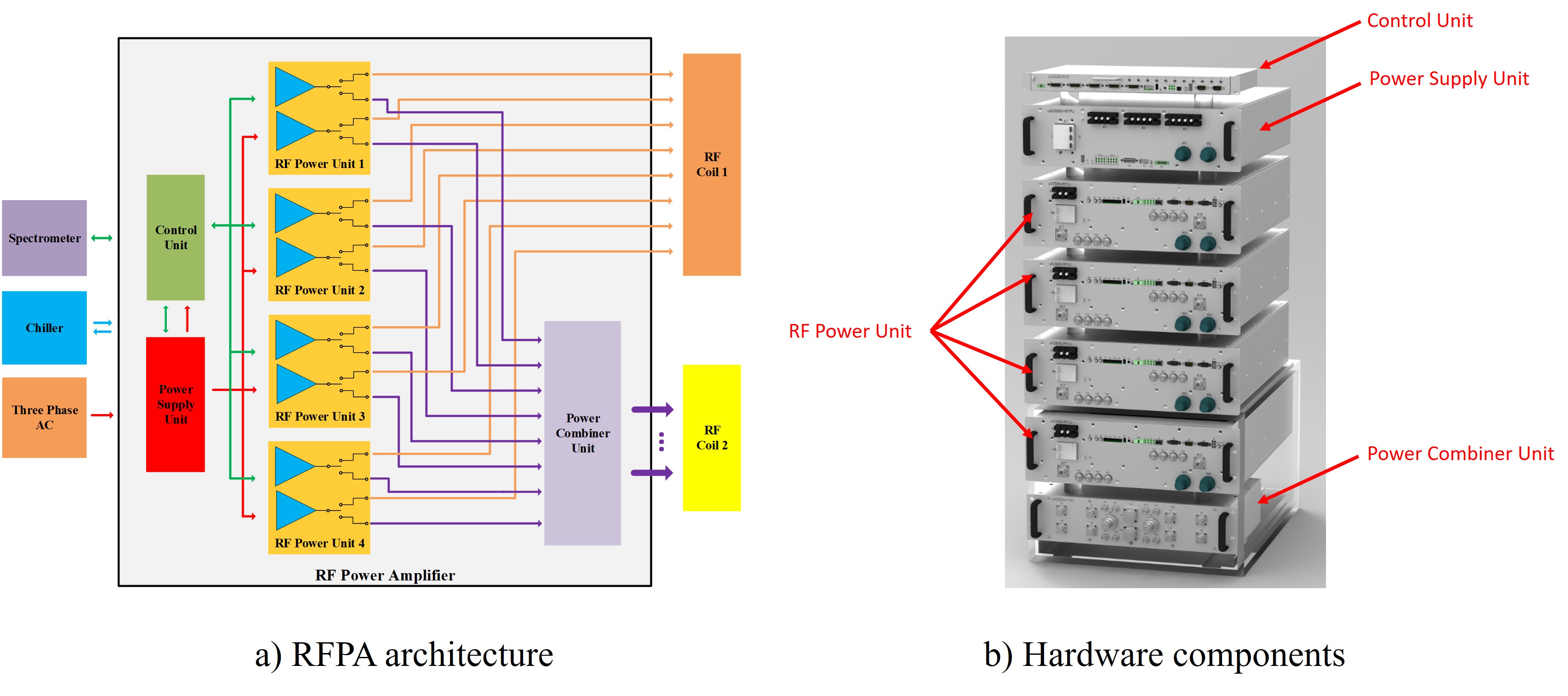
The RFPA design consists of control unit, power supply unit, power combiner unit and RF power units. The hardware architecture is shown in figure 1.The controller unit controls and monitors the power supply unit and RF power unit through control interface. The RF power unit is the core module which generates the required RF power according to the digital RF waveform from spectrometer in the MRI system. The power supply unit converts the three-phase AC power into the DC power required by the Control unit and the RF power unit. The four RF power units encapsulate eight independent RF channels, with the output of each RF channel leading directly to the RFPA output or to the power combiner via a switch consisting of PIN DIODEs. In this work, the power combiner unit has two Wilkinson combiners of 4-to-1. The power combiner unit is a FRU(field replaceable unit) and can be replaced with other types of combiners, such as several 2-to-1 combiners, etc. The introduction of the power combiner unit allows the number of output channels to be selected among 1/2/4/8.
High Power RF LDMOS (MRFX1K80H, NXP) is selected as the key power device based on theoretical calculation and simulation, each LDMOS can deliver 2kW peak power with dedicated designed output matching network. To avoid stress inconformity in the Wilkinson combiner, LDMOS devices work in equilibrium. The overall efficiency of the Class AB RF circuit is over 50% and water cooling heatsink is adopted.
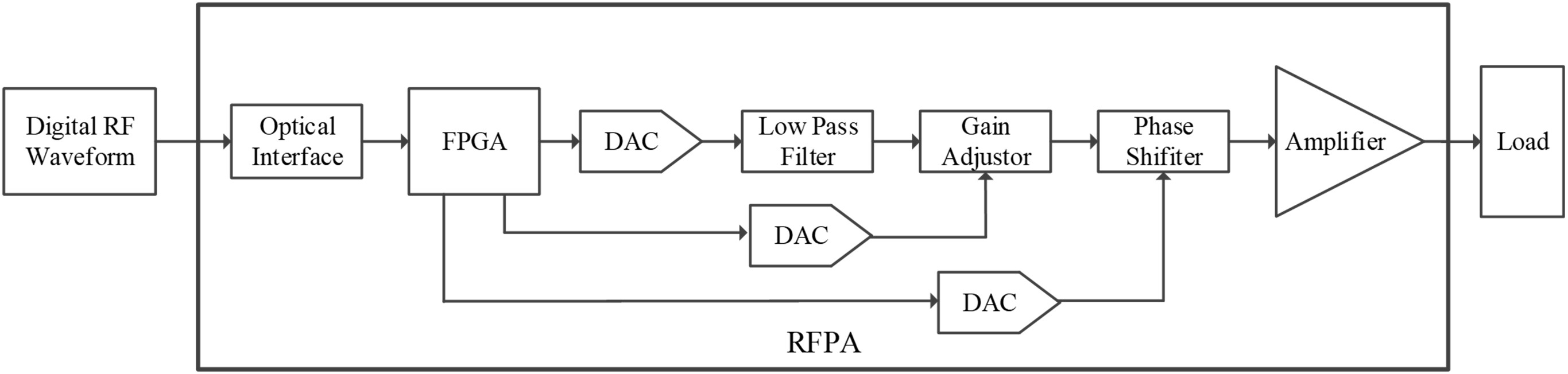
Accurate and fast imaging requires high linearity in the RF transmission system. A pre-distortion algorithm is developed to compensate the nonlinear characteristic of the RFPA (Figure 2). To avoid loss and distortion caused by traditional analog RF signal transmission, the digital RF waveform is transmitted to the RFPA via optical interface, the gain and phase is adjusted according to the RF input data and look-up table stored in the FPGA.
Results
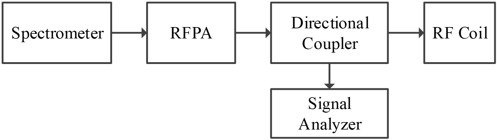
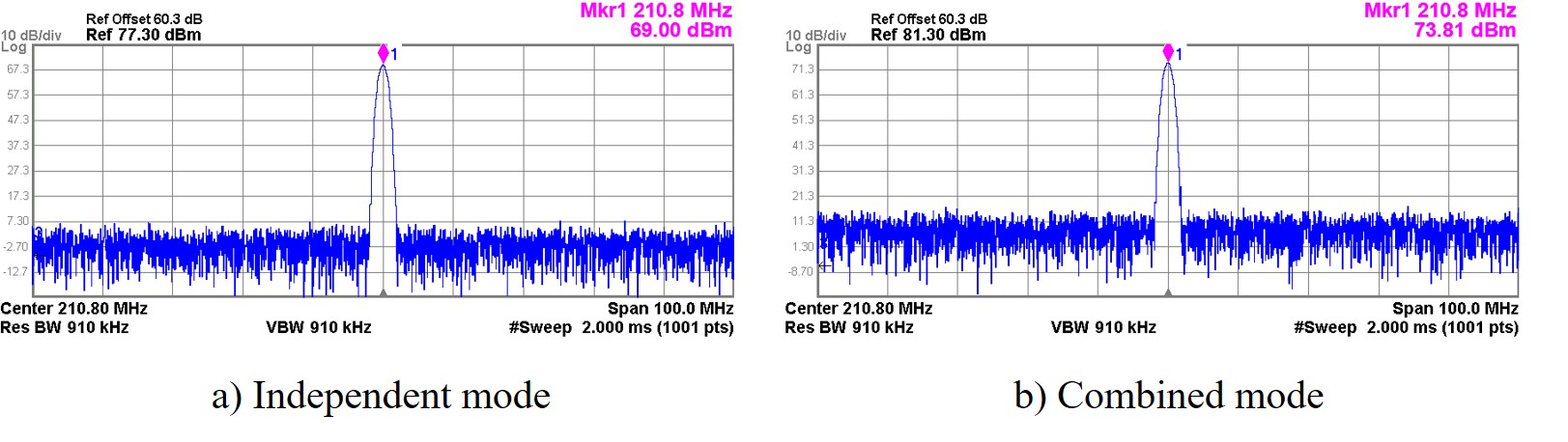
A new RFPA prototype for UHF MRI is designed and tested on a whole body 5T scanner (United Imaging Healthcare, Shanghai, China). The measurement setup is shown in figure 3. RFPA generates the required RF power according to the digital RF waveform from spectrometer in the MRI system, the RFPA outputs are detected by directional coupler (BN800468, SPINNER) and analyzed by signal analyzer (N9010A, KEYSIGHT).When RFPA is configured into independent mode, the RFPA has 8 independent outputs with 8kW(69dBm) peak power capability per channel, when configured into combined mode, there are 2 independent outputs with 24kW(73.81dBm) peak power capability per channel(Figure 4).
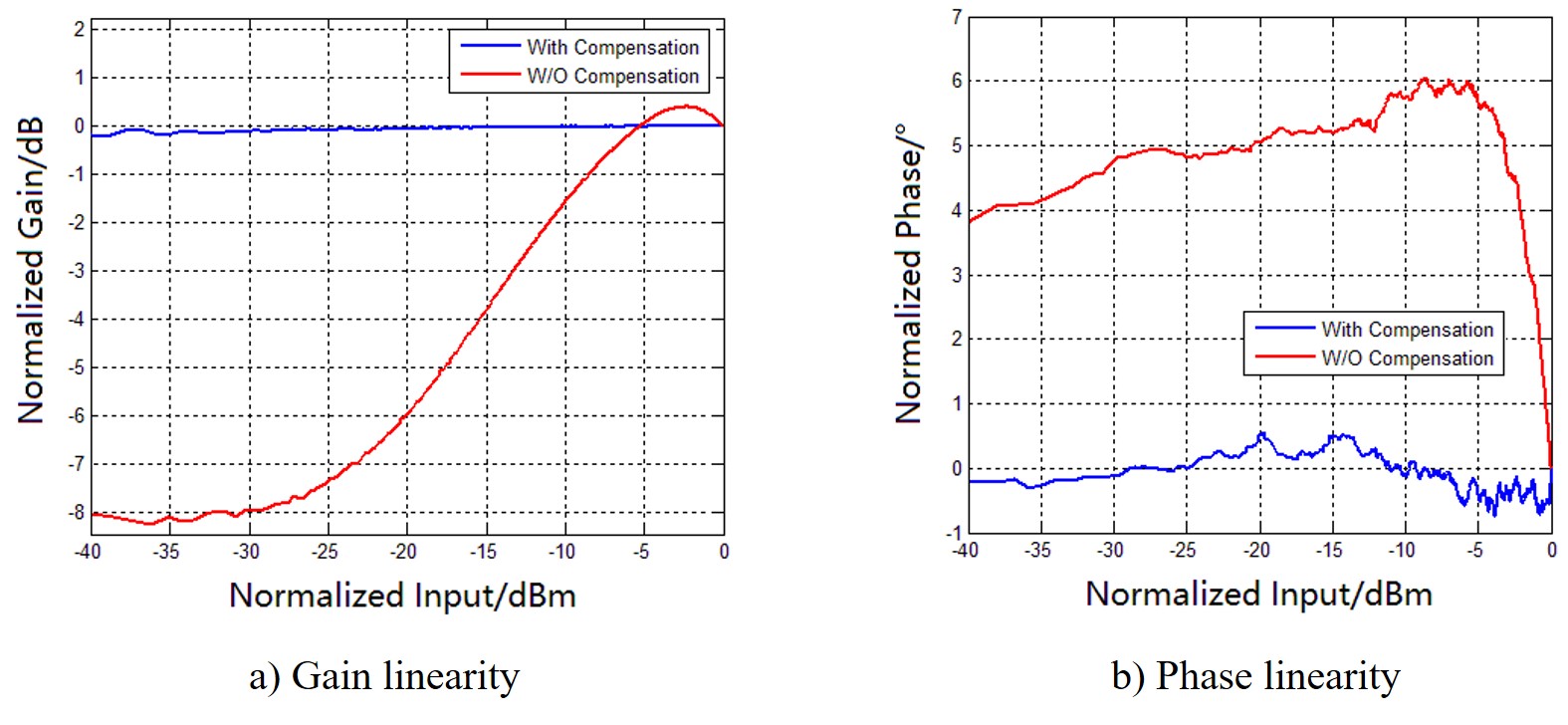
A high-precision pre-distortion compensation strategy is developed in order to make the gain/phase fluctuation within 0.5dB/5°. Figure 5 compares the RFPA linearity with and without compensation.
Within the dynamic range of 40 dB, the gain/phase fluctuation is less than 0.3dB/ 2° and meets the design specification.
Conclusion
The test results show that the output power capability, linearity and output stability of a new RFPA meet the UHF MRI design requirement, the amplitude and phase of each channel can be adjusted independently; the number of channels can be configured according to the RF coil requirements. The coupling between channels and the adaptability of high VSWR loads need to be verified and optimized with more RF coils and applications in the future.Acknowledgements
This work is supported by National Key R&D Program of China N0.2017YFC0108800.References
1. Erturk MA, Li X, Van de Moortele PF, et al. Evolution of UHF Body Imaging in the Human Torso at 7T: Technology, Applications, and Future Directions. Top Magn Reson Imaging. 2019;28(3):101-124.
2. Stephan Orzada, Mark E. Ladd, Harald H. Quick. A 2kW RF power amplifier for 7T proton imaging with digital pre-distortion. ISMRM 2020 Abstract 4072
3. Natalia Gudino, Jacco A de Zwart, Jeff H Duyn. Eight‐channel parallel transmit‐receive system for 7 T MRI with optically controlled and monitored on‐coil current‐mode RF amplifiers. Magn Reson Med. 2020;84(6):3494-3501
Figures