1584
New commercial 8Tx/16RX array for Clinical 7T Cardiac MRI: initial experience1Chair of Molecular and Cellular Imaging, University Hospital Würzburg, Comprehensive Heart Failure Center, Wuerzburg, Germany, 2Department of Internal Medicine I, Cardiology, University Hospital Würzburg, Wuerzburg, Germany
Synopsis
7T cardiac MRI is a novel field with the potential to increase the physical sensitivity and diagnostic value of the clinical cardiac images. Multiple elements transmit/receive phased array coils in combination with parallel transmit RF-technology allow for an improvement of the image quality at ultra-high-field (B0≥7T) field strength. In this work, we present initial experience with a new commercial 8Tx/16Rx thorax array coil operating in a “pTX-Compatibility Mode” of the scanner for cardiac MRI at 7T.
Introduction
7T cardiac MRI (CMR) is a novel research field with the potential to increase the physical sensitivity and diagnostic value of clinical cardiac images when compared to clinical field strengths. Multiple elements transmit/receive phased array coils in combination with parallel transmit (pTx) RF-technology promises for an essential improvement of the image quality in the ultra-high-field (B0≥7T) MRI. Adjustment of the magnitudes and phases of the driving voltages for the individual elements allows for the suppression of destructive interferences of the electromagnetic field and promises better homogeneity of image contrast within the heart. However, the routine application of the 7T cardiac arrays in full-pTX mode is currently not feasible due to the complexity of both the B1-shimming process and, especially, on-line analysis of the SAR-safety for each specific subject. We present initial results on a new commercial 8Tx/16Rx cardiac array designed to operate in a virtual single-channel (“pTX-compatibility”) mode.Materials and Methods
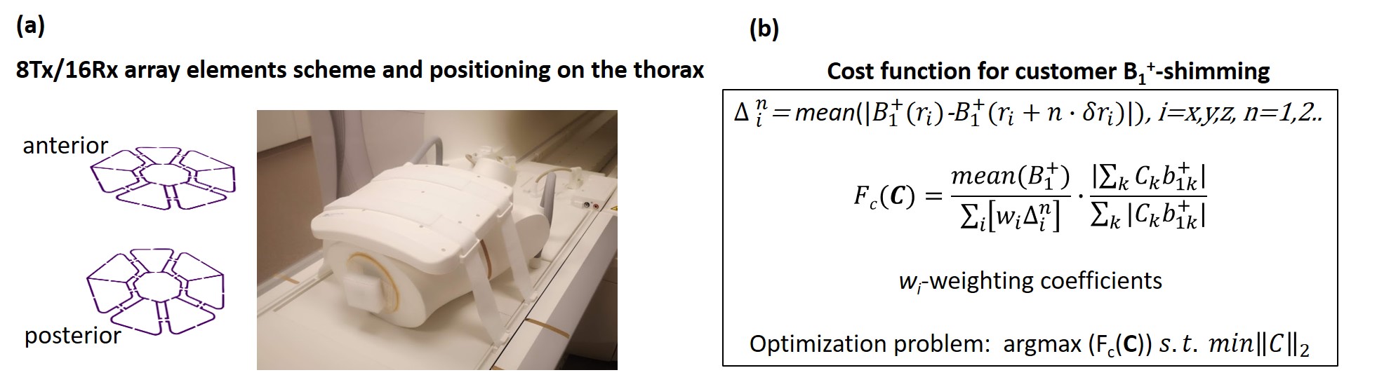
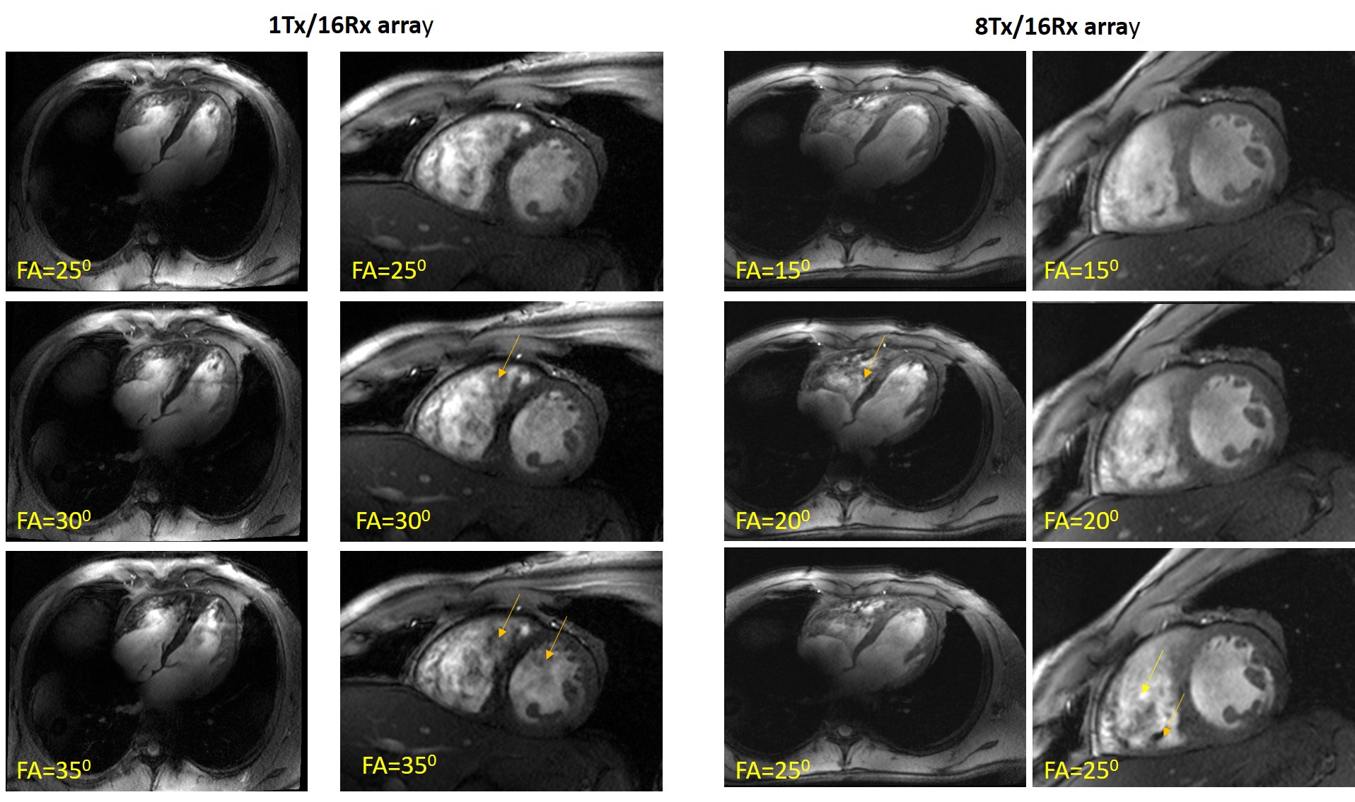
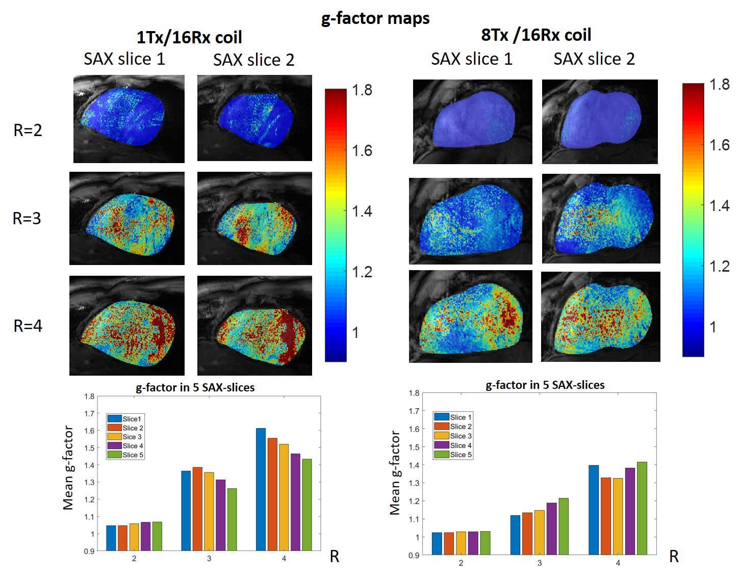
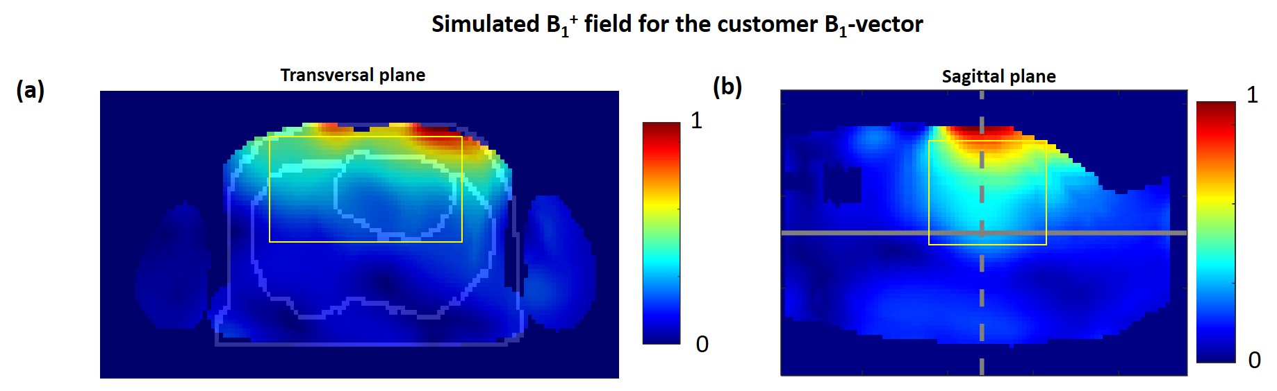
Measurements were performed with the approval of the local ethics committee using a Magnetom™ “Terra” 7T MR-scanner (Siemens Healthineers, Erlangen) and a new commercial 8Tx/16Rx cardiac array (RAPID Biomedical, Rimpar, Germany) with central symmetry of the coil elements (Figure 1a) which has been tested earlier as a 1Tx-channel-prototype [1]. The “pTX-compatibility mode” mode is a concept allowing usage of pTX-arrays in virtual single TX mode with predefined B1 phases of the voltages driving the RF-power amplifier. This specific “phase vector” is fixed in the coil configuration but can be changed by qualified researchers. This allows for, on one hand, a SAR-safe “push-button” application of the array in clinical routine and, on the other hand, keeping flexibility for the targeted B1 adjustment for a specific subject or patients cohort. As an initial test, a default phase vector set by the vendor was used. The voltage of an 1800 pulse with 1 ms duration was determined by an integrated scanner flip angle calibration routine. CMR was performed using vendor-provided GRE-sequence [1]. Cardiac triggering was performed using the scanner’s integrated ECG-monitoring system. Imaging parameters were TR/TE=59/3.6ms, image matrix=288x228 with FOV=340x320mm, and GRAPPA acceleration factor R=3. The flip-angle (FA) was varied to adjust optimal blood-tissue contrast such that minimal blood-flow related image artifacts were observed. The study protocol included localization scans, four-chamber, and short-axis-view CINE stacks, respectively, with 30 cardiac phases (retrospective ECG triggering). Technical coil characterization was done using the vendor’s “coil utility” protocol which comprises of acquisition and reconstruction of SNR and g-factor maps. For comparison, the same protocol was repeated using a commercial 1Tx/16Rx cardiac array (MRI.TOOLS, Berlin, Germany) To explore the potential of the new array concerning full pTX-based B1-shimming a customer-defined complex B1-vector was computed using the electromagnetic model of the array. The EM-simulations of individual Tx-channels were done using CST MIcrowave Studio (Dassault Systeme) in two human models “Duke” and “Ella” (IT’IS Foundation, Zürich). The dedicated cost-function (Figure 1b) for the B1-vector optimization was designed taking into account both array geometry and B1-profiles of individual Tx-channels. It comprises (i) maximization of the mean value of combined B1-field (ii) minimization of the weighted combination of the mean gradient of B1 in x,y,z directions, and (iii) maximization of the transmit efficiency.Results
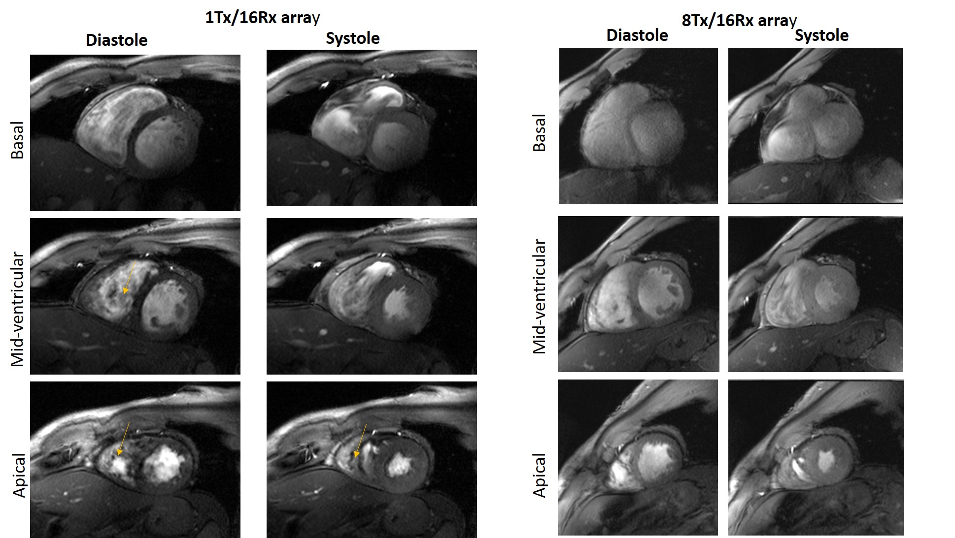
Figure 2 shows the comparison of the four-chamber and short-axis views, respectively, for both coils at flip angles optimized for each coil. Figure 3 shows a comparison of selected slices from a short-axis-view stack from basal, mid-ventricular, and apical positions at systole and diastole. Figure 4 shows the comparison of g-factor maps of both arrays for short-axis and long-axis views. Both long and short-axis views demonstrate an increase of flow-induced artifacts with increasing flip-angle for both arrays. The overall amount of such artifacts was found to be lower for the new array probably due to a lower gradient of B1-field in the anterior-posterior direction. The maximal FA allowed by the SAR-monitor for the same volunteer (84kg) at the same protocol was 420 for the new array using the default B1-vector and 400 for the 1Tx. The g-factor maps of the tested 8Tx/16Rx array demonstrate lower average values at acceleration factors R=3 and 4 compared to the 1Tx array. Figure 5 demonstrates the results of the optimization of the B1-field of the new array in the heart region of the “Duke” human-body model.Discussion
Overall we observed high coil efficiency and more homogenous image quality which probably is a result of a more homogeneous B1-profile. The observed improvement of the g-factor most probably is a result of the symmetrical arrangement of the coil elements which allows for a more efficient acceleration at oblique slice orientation. We expect that the usage of a dedicated customer-calculated B1-vector in the near future will provide further improvement of the homogeneity of the B1-profile and, thus, ensure even more homogeneous image contrast, particularly in the posterior and lateral heart wall.Conclusion
The initial experience of measurements and preliminary analysis is promising and suggests a high potential of the new commercial 8Tx cardiac array using the virtual single-channel Tx mode with user-defined B1-phase vector. Further optimization for clinical usage can be done using dedicated customer B1-vectors computed for specific patient cohorts.Acknowledgements
Financial support: German Ministry of Education and Research (BMBF, grants: 01EO1004, 01E1O1504).
Stimulating discussions with Robin Heidemann and Ralph Kimmlingen (Siemens Healthineers), Titus Lanz, and Carsten Kögler (Rapid Biomedical) are greatly acknowledged.
References
[1] Terekhov, M, Elabyad, I, Kögler, C, et al. „Customized B1+-Shaping using multi-Channel transceiver array prototype for 7 T cardiac MRI with central elements symmetry“. Proc 28th Intl. Soc. Mag. Reson. Med. (Virtual meeting, 2020)Figures