1583
Development of a Microstrip Tx Coil Module for 7T MRI1University of Pittsburgh, Pittsburgh, PA, United States
Synopsis
A 7T microstrip RF coil was designed based on the Tic-Tac-Toe (TTT) concept that has previously shown homogeneity and load-insensitivity. Simulations were performed to compare B1+ distributions between the microstrip TTT and standard TTT coils. A 4-channel microstrip coil was assembled and B1+ maps were acquired at 7T. Nearly equivalent B1+ distributions were observed, indicating the potential for using a highly dense microstrip array to provide excellent homogeneity and reduction of SAR while enabling unique designs, such as conforming to the anatomy of interest.
Introduction
The Tic-Tac-Toe (TTT) family of RF coils1-6 has shown to provide homogeneous and load-insensitive B1+ for 7T MRI. Several groups have investigated using microstrip Tx coils at 7T.7,8 This work presents a novel microstrip antenna design that is simpler to fabricate and more versatile than the current TTT design and provides equivalent B1+.Methods
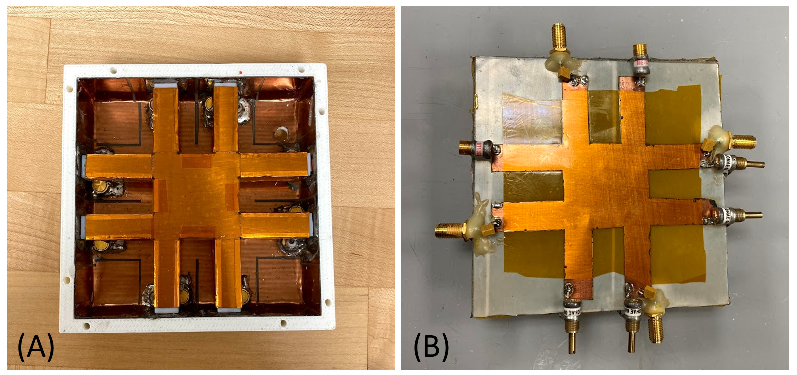
A 4-channel microstrip panel (Figure 1b) was designed based on the existing TTT concept1-6 (Figure 1a). Finite difference time domain (FDTD) simulations with a transmission line model were performed using in-house developed software. The coil was tuned and matched by adjusting the values of the capacitors in the simulation.The simulation of a 4.25 in x 4.25 in microstrip TTT coil was compared to the simulation of the standard TTT coil of equivalent size (Figure 2a-b, Figure 3a-b). The standard TTT panel has been used in a double-row octagon arrangement which has been shown to improve B1+ homogeneity and SAR in the human head and provides more degrees of freedom for RF shimming.5,6
A 4.25 in x 4.25 in microstrip panel was assembled using a Rexolite plastic substrate and copper sheets for the ground plane and conducting TTT element. Variable capacitors were used for tuning and matching to a center frequency of 297.2 MHz and an impedance of 50Ω. B1+ maps were acquired on a spherical saline phantom using a 7T MRI scanner (Siemens, Erlangen, Germany) using a Turbo-FLASH sequence with the following parameters: TR/TE = 2000/1.16 ms; TA = 12 min; flip angle from 0° to 90° in 18° increments; 3.2mm isotropic resolution. Channels were combined with 90° phase shifts for quadrature excitation.
Results
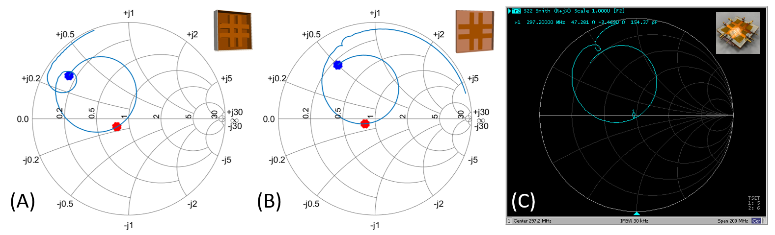
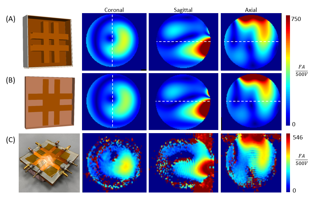
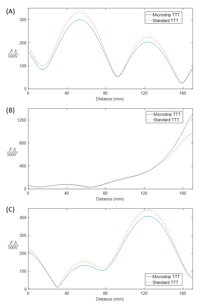
Figure 2 shows Smith charts from the simulations of the standard TTT coil and the microstrip TTT coil as well as the experimental Smith chart for the microstrip coil. Figure 3 compares the B1+ field distributions from the simulations of the standard TTT coil, simulations of the microstrip TTT coil, and experimental B1+ maps from the microstrip TTT coil. Central slice profiles of B1+, outlined by the dashed lines in Figure 3a-b, are displayed in Figure 4 to compare the simulated B1+ of the standard TTT and microstrip TTT coils.Discussion and Conclusion
B1+ distributions are consistent between the simulated standard TTT and microstrip TTT and between the simulations and experimental B1+ maps of the microstrip TTT. Overall differences in signal intensity between the simulated and experimental B1+ maps (~27%) can be attributed to losses in the coil, cables, connectors, TR switch, and power splitters.The microstrip TTT coil shows nearly identical B1+ field distributions to the standard TTT coil, which, when used in a multichannel array, is effective at reducing SAR and providing homogenous B1+ in the human head at 7T.5,6 The microstrip design, however, is simpler to construct than the standard TTT design and enables unique geometries, such as a cylindrical or conformable design. Future work will explore the design, simulation, and construction of multichannel microstrip TTT arrays.
Acknowledgements
This work was supported by the National Institutes of Health under award numbers R01MH111265 and R01AG063525 and by the National Science Foundation Graduate Research Fellowship under Grant No. 1747452. This work used the Extreme Science and Engineering Discovery Environment (XSEDE), which is supported by National Science Foundation grant number ACI-1548562 and was also supported in part by the University of Pittsburgh Center for Research Computing through the resources provided.References
1. Kim, J., et al. (2016). “Experimental and numerical analysis of B1+ field and SAR with a new transmit array design for 7T breast MRI.” J Magn Reson 269: 55-64.
2. Krishnamurthy, N., et al. (2019). “Computational and experimental evaluation of the Tic-Tac-Toe RF coil for 7 Tesla MRI.” PLoS ONE 14(1): e0209663.
3. Santini, T., et al. (2018). “In-vivo and numerical analysis of the eigenmodes produced by a multi-level Tic-Tac-Toe head transmit array for 7 Tesla MRI.” PLoS ONE 13(11): e0206127.
4. Santini, T., et al. (2020). “Improved 7 Tesla Transmit Field Homogeneity with Reduced Electromagnetic Power Deposition Using Coupled Tic Tac Toe Antennas.” bioRxiv: 2020.2011.2006.371328. Accepted for publication in Scientific Reports.
5. Santini, T., et al. (2017). “64-channel Double-Octagon Tx Head Coil for 7T Imaging.” In Proc. of the 25th International Society of Magnetic Resonance in Medicine Annual Meeting, Honolulu, Hawaii, USA.
6. Santini, T., et al. (2019). “Homogeneous 64-channel RF transmit array for brain imaging at 7T, 9.4T, and 10.5T.” In Proc. of the 27th International Society of Magnetic Resonance in Medicine Annual Meeting, Montreal, Quebec, Canada.
7. Wu, B., et al. (2010). “Shielded microstrip array for 7T human MR imaging.” IEEE Trans Med Imaging 29(1): 179-184.
8. Wang, C. and G.X. Shen. (2006). “B1 field, SAR, and SNR comparisons for birdcage, TEM, and microstrip coils at 7T.” J Magn Reson Imaging 24(2): 439-443.
Figures