1582
Toward Enhanced Transmit Performance of Rectangular Dielectric Resonator Antenna Arrays for 7-T MRI Using Loop/Dipole Coupling Scheme
Daniel Wenz1,2
1CIBM Center for Biomedical Imaging, Lausanne, Switzerland, 2Animal Imaging and Technology, Ecole Polytechnique Federale de Lausanne (EPFL), Lausanne, Switzerland
1CIBM Center for Biomedical Imaging, Lausanne, Switzerland, 2Animal Imaging and Technology, Ecole Polytechnique Federale de Lausanne (EPFL), Lausanne, Switzerland
Synopsis
This study investigates a loop-dipole coupling scheme as a new approach to excite orthogonal dielectric modes in a rectangular dielectric resonator antenna for MRI at 7T. A rectangular dielectric resonator antenna was simulated, built and its performance was evaluated in phantom experiments using two coupling schemes: dipole-only and loop-dipole. It was found that the loop-dipole coupling scheme can substantially enhance not only transmit performance of a single element, but also of an array of rectangular dielectric resonator antennas (transmit field efficiency gain of 35%).
Introduction
Dipole antennas play a key role in ultrahigh (UHF) MRI by providing high transmit efficiency and signal-to-noise ratio (SNR) especially for deeper-located anatomical structures1,2. To use dipole antennas in a multi-channel array configuration, rectangular dielectric blocks are often used to physically shorten the antennas3,4. Dipole antenna can couple to a rectangular dielectric block and excite dielectric modes which have a critical impact on overall transmit field pattern and efficiency5. The orthogonality of electromagnetic fields of a dipole antenna and a loop element enables a very high level of isolation when these two elements are placed exactly one above the other6. A small loop element was used in the past to couple to different modes of dielectric resonator antennas7-9. Yet, a loop/dipole coupling scheme to excite orthogonal dielectric modes in a rectangular dielectric resonator antenna (RDRA) for 7T MRI has not been investigated so far. Therefore, the aim of this work was to design a loop/dipole-fed rectangular dielectric resonator antenna and to compare its transmit performance with a dipole-fed rectangular dielectric resonator antenna.Methods
Numerical electromagnetic field simulations in a spherical phantom (radius = 90 mm, dielectric constant εr = 50.6, conductivity σ = 0.66 S/m,) were performed using a finite-difference-time-domain method of Sim4Life (Sim4Life, Switzerland). The dimensions of the rectangular dielectric block (εr = 80 and σ = 0.065 S/m) were (160x70x18)mm3. Dipole antenna was fully immersed in D2O (Fig. 1). The distance between the antenna and the bottom of the dielectric block was 10 mm. Dipole antenna length per arm was 52.5 mm mm and conductor width was 5 mm. Loop diameter was 15 mm and cooper wire diameter was 1 mm. The distance between the loop and the top surface of the dielectric block was 25 mm. Transmit field (B1+/√Pin) and specific absorption ratio (SAR) efficiency (B1+/√SAR10g) were evaluated (Pin is the input power and SAR10g is maximum local SAR averaged over 10g). An 8-channel (dipole-coupled) and a 16-channel (loop-dipole coupled) rectangular dielectric resonator antenna arrays were compared in simulations. Both arrays were driven in a circularly polarized (CP) mode. In the experiments, a box made of poly(methyl methacrylate) filled with D2O was used. Two transmit/receive switches (MR CoilTech, UK) and a 1:2 power divider (MRI.TOOLS, Germany) were used to interface the loop-dipole coupled RDRA to a 7T MR scanner (Magnetom, Siemens) while for the dipole-coupled counterpart only one transmit/receive switch was used (no power divider). MR experiments in a spherical phantom were conducted using a two-dimensional (2D) gradient-echo sequence: TR/TE=8.6/4.0 ms, Nslices = 10, slice thickness = 3.0 mm, Navg = 10, FOV = 250 x 250 mm2, transmit voltage = 7.9V (reference 50V).Results
To compare transmit performance of the loop-coupled and loop-dipole-coupled rectangular dielectric resonator antenna, electromagnetic field simulations (Fig.1) and phantom experiments were performed (Fig.2). It was found in simulations that B1+ and SAR efficiency along a selected profile (the central line) was higher for the loop-coupled RDRA (Fig.1). Preliminary phantom experiments showed that signal intensity in particular regions of the spherical phantom was significantly higher for the loop-dipole-coupled RDRA than for its dipole-coupled counterpart (Fig.3). To evaluate which element would perform better as a building block of an array, two arrays were compared in the simulations: an 8-channel (dipole-coupled) and a 16-channel (loop-dipole-coupled) array (Fig.4). For the latter, intra-element coupling was well below -20dB for all of the elements excluding the adjacent ones: loop/loop (-9.2dB), dipole/dipole (-11.0dB), loop/dipole (-14.1dB). The 16-channel array yielded significantly higher B1+ (+35%) and SAR (+9%) efficiency in the center of the spherical phantom.Discussion and Conclusion
This study demonstrates for the first time that using a loop-dipole coupling scheme in a rectangular dielectric resonator antenna for MRI at 7T can provide a significant transmit performance gain when compared with a dipole-only coupling scheme. The simulations showed that using loop/dipole coupling scheme can provide higher B1+ and SAR efficiency than the dipole-only for a single element (Fig.1). Simulations were confirmed in preliminary phantom experiments showing that loop-dipole coupling scheme provides substantially higher signal intensity in particular regions of the spherical phantom with no signal intensity decrease in other regions of the phantom (Fig.2,3). To conclude, this approach can be used to substantially enhance B1+ efficiency of an 8-channel dipole-fed rectangular dielectric resonator array (35% higher B1+ and 9% higher SAR efficiency in the center of the phantom). Future work will focus on the optimization of particular parameters of the loop-dipole-coupling scheme. Moreover, dielectric constant, which was used in this work, can be optimized for different clinical applications and it is anticipated that this aspect will be further explored as.Acknowledgements
We acknowledge access to the facilities and expertise of the CIBM Center for Biomedical Imaging, a Swiss research center of excellence founded and supported by Lausanne University Hospital (CHUV), University of Lausanne (UNIL), Ecole polytechnique fédérale de Lausanne (EPFL), University of Geneva (UNIGE) and Geneva University Hospitals (HUG).References
1. Raaijmakers AJE, et al. The fractionated dipole antenna: A new antenna for body imaging at 7 Tesla. Magn Reson Med (2016).2. Lattanzi R et al Approaching ultimate intrinsic signal-to-noise ratio with loop and dipole antennas. Magn Reson Med (2018).
3. Raaijmakers AJE, et al. Design of a radiative surface coil array element at 7 T: the single-side adapted dipole antenna. Magn. Reson. Med (2011).
4. Winter L, et al. Design and Evaluation of a Hybrid Radiofrequency Applicator for Magnetic Resonance Imaging and RF Induced Hyperthermia: Electromagnetic Field Simulations up to 14.0 Tesla and Proof-of-Concept at 7.0 Tesla. Plos One (2013).
5. Wenz D and Gruetter R, Dielectrically-Shortened Dipole Antennas for MRI at 7.0 T: Thick or Thin? Proc. Intl. Soc. Mag. Reson. Med. 28 (2020).
6. Erturk A, et al. 16‐channel combined loop‐dipole transceiver array for 7 Tesla body MRI. Magn Reson Med (2017).
7. Aussenhofer SA and Webb AG, Design and evaluation of a detunable water-based quadrature HEM 11 mode dielectric resonator as a new type of volume coil for high field MRI: Design and Evaluation of a Detunable Quadrature HEM 11. Magn. Reson. Med (2012).
8. Aussenhofer SA and Webb AG, An eight-channel transmit/receive array of TE01 mode high permittivity ceramic resonators for human imaging at 7T. J. Magn. Reson (2014).
9. O’Reilly T, et al. Modular transmit/receive arrays using very-high permittivity dielectric resonator antennas: Very-High Permittivity DRA Arrays. Magn Reson Med (2018).
Figures
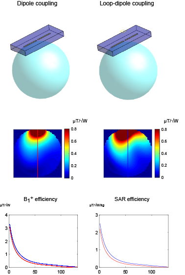
Fig. 1. Loop- vs. loop-dipole-coupled rectangular
dielectric resonator antenna: the single element comparison.
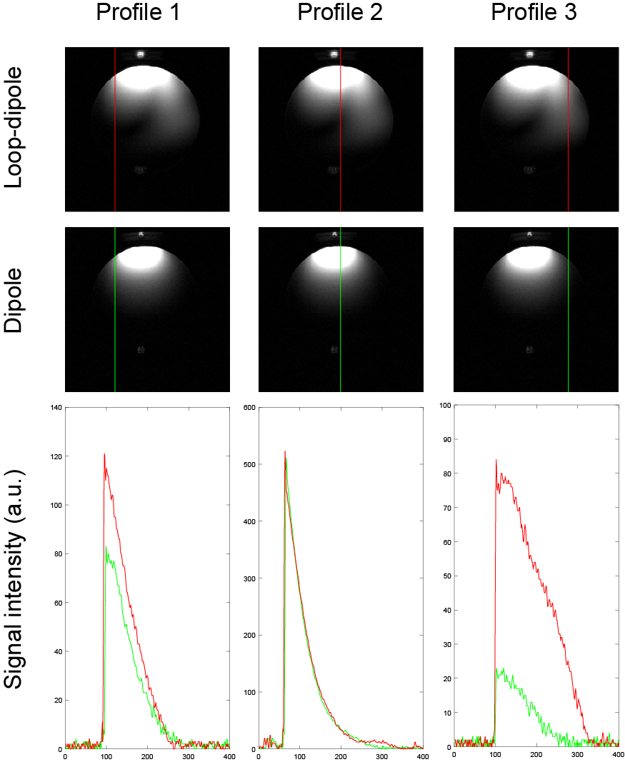
Fig. 2. Phantom measurements: MR images obtained for a single-element
loop- and loop-dipole-coupled rectangular dielectric resonator antenna. Three
different profiles were selected and signal intensity as a function of distance
was shown below.
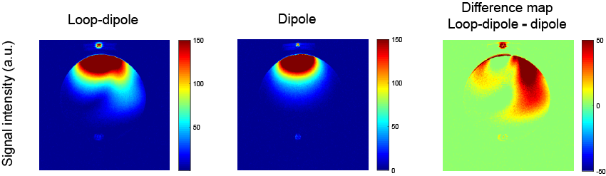
Fig. 3. Signal intensity images and difference map between loop-dipole and
loop-coupled rectangular dielectric resonator antenna.
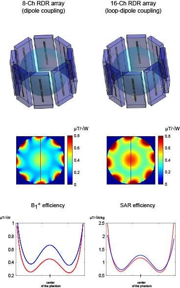
Fig. 4. Transmit performance of the 8-channel
dipole-fed rectangular dielectric resonator (RDR) array compared with the
16-channel loop-dipole coupled RDR array (circularly polarized mode). The 16-channel array yielded significantly higher B1+
(+35%) and SAR (+9%) efficiency in the center of the spherical phantom.