1581
Asymmetric ring birdcage coil for volume excitation1Healthcare Business Unit, Hitachi, Ltd., Tokyo, Japan
Synopsis
Design of asymmetric ring diameter birdcage volume coil has been studied by electromagnetic filed simulations. Even if the diameter of the front and the rear rings of the birdcage coil is changed to some extent with respect to the cylindrical RF shield, the uniformity in the Z direction can be maintained by changing the width of the front and rear rings. Increasing the gap between the ring and the RF shield has an advantage in efficiency even applied on one side of the ring.
Introduction
Since the first publication in 1985 [1], various birdcage coils have been created, such as those with a larger ring radius [2], oval shapes [3], and shapes that match human cross-sections [4]. The RF transmit coil needs to be confined in a narrow space gap between the gradient coil and the patient space. The size of the space gap between the RF shield and the transmit coil pattern is greatly related to the efficiency of the transmit coil. Reference [2] states that by making the diameter of the ring part larger than that of the rung part, there is an advantage in reducing the electric field and lowering the SAR. However, increasing the diameter of the ring part reduces the space gap between the RF shield and the ring, which makes the transmit efficiency worse. The human body has no symmetry from the head to foot, and the tunnel-type MRI device also has no symmetry because the subject is inserted from one side of the tunnel. Therefore, it is possible that one can find merit by changing the size of two rings of the birdcage coil. In this report, we pursued a design that balances transmit efficiency, SAR, and patient comfort by increasing the diameter only on the front side of the rings of a birdcage.Method
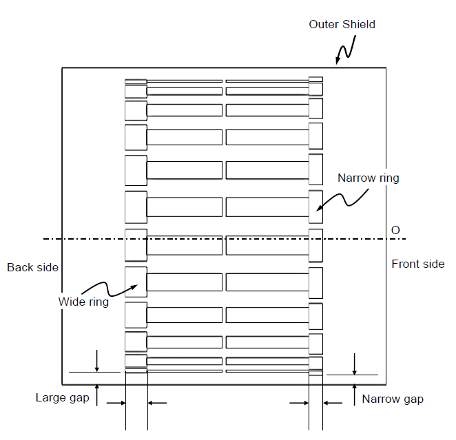
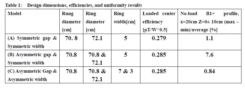
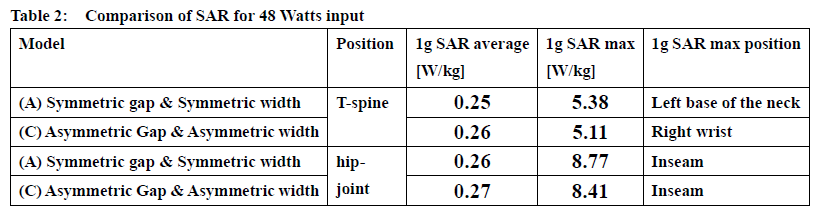
Empire XPU(IMST GmbH, Germany) was used for the electromagnetic field simulation. The error of the simulated B1+ efficiency is about 5% evaluated with measured values using actual MRI systems. The high-pass birdcage coils were modeled with 24 rungs and a rung diameter of 70.8 cm. The diameter of the RF shield (copper) is 76.6 cm. Three types of models were made: the gaps between the RF shield and the front and the rear ring are symmetric and the width of the front and the rear rings is symmetric (model A), the gap is asymmetric but the ring width is symmetric (model B), and the gap and ring width are both asymmetric (model C). The diameters are summarized in Table 1. These models were tuned to a frequency of 1.5 Tesla. For the asymmetric ring width model(C), we found a ring width with good uniformity in the Z-axis direction by changing the ring width but with the capacitor value being symmetric. A cylindrical phantom (30cm dia. & 50cm length, 0.613 S/m) was used for evaluating transmit efficiency. Transmit efficiency was evaluated with the value of B1+ at the center of the phantom. As an evaluation of uniformity in the Z-axis direction, (maximum-minimum)/average value of unloaded B1+ values along -10cm <Z< 10cm line (20cm away from the central Z-axis) were used. To evaluate the effect of the asymmetric rings on SAR, two landmarks, T-spine and Hip-Joint of Fats model (IT'IS Foundation, Switzerland, body weight 120 kg) were evaluated. The landmarks of T-spine and Hip-Joint are where the lower arms of Fats approach to the ring at the front and the rear sides, respectively. Of the three models shown in Table 1, the SAR was evaluated for only two models (A & C), because of good comparable uniformity among them.Result and discussion
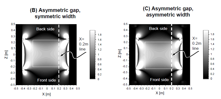
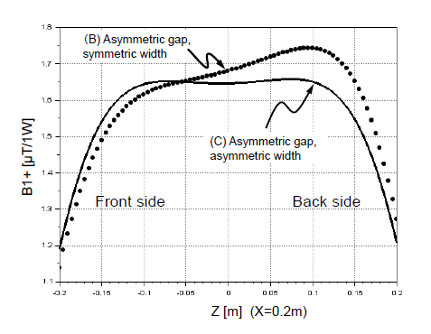
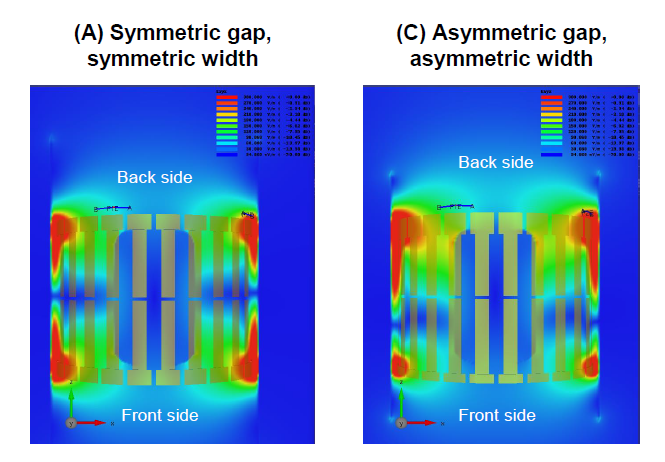
The front ring with the larger diameter and the narrower ring width as shown in Fig. 1 improved the uniformity in the Z-axis direction. Fig. 2 shows the B1+ intensity map of the central coronal plane. Table 1 shows the transmit efficiency of the center. The transmit efficiency at the center of models B and C was improved by about 2% compared to model A. Table 1 also shows a quantitative uniformity evaluation along a line. Fig. 3 shows the B1+ profile at 20 cm away from the center. The symmetry and uniformity of B1+ in the Z direction are better in model C than in model B. Fig. 4 shows the coronal electric field map of model A and C. Interestingly, the B1+ map shows almost the same distribution for both models B and C, but the electric field maps are very different. Normally, the electric field of birdcage coils becomes zero at the plane of Z = 0, but in model C, the electric field becomes zero at around Z = -10 cm. Table 2 shows the maximum values of 1g average SAR, the places where the maximum is taken, and the average SAR values when the Fats model is inserted and irradiated at 48 watts for models A and C. Although there was concern about the effect of a large difference in the electric field distribution in Fig. 4, the SAR of model C was very similar to that of model A.Conclusion
It was found that even if the diameter of the front and rear rings of the birdcage coil is changed to some extent to the cylindrical RF shield, the uniformity in the Z direction can be maintained by changing the width of the front and the rear rings. It was found that increasing the gap between the ring and the RF shield has an efficiency advantage even applied on one side of the ring.Acknowledgements
No acknowledgement found.References
[1] C. E. Hayes, et. al., "An efficient, Highly Homogeneous Radiofrequency Coil for Whole-Body NMR Imaging at 1.5T", J. Magn. Reson., 63, 622-628 (1985)
[2] D. J. Weyers, et. al., patent US 7688070 B2 (2010)
[3] Y. Soutome, et. al., patent JP 2012-217675A (2012)
[4] N. D. Zanche, et. al., “Asymmetric Quadrature Split Birdcage coil for hyperpolarized 3He Lung MRI at 1.5T”, MRM 60, 431-438 (2008)
Figures