1580
A Comparative Study Highlighting a Novel UHF MRI Volume Body Coil Design1Radiology, Weill Cornell Medicine, New York, NY, United States, 2General Electric Healthcare, Aurora, OH, United States
Synopsis
We designed a novel 2D cylindrical high-pass ladder (c-HPL) volume body coil by adding a second dimension in S-I direction to the 1D birdcage concept, given that the latter fails at 7T body dimensions. We compared its performance to the (non-functional) 1D birdcage and transverse electromagnetic (TEM) designs. In silico results showed improved B1 homogeneity (inhomogeneity of 15.9%) with lower specific absorption rate (SAR) and better SAR efficiency (0.743 μT/W∙√kg). The proposed architecture is a promising candidate for UHF MRI applications where the current lack of a built-in body coil hinders the modality from gaining full clinical acceptance/approval.
Introduction
Ultra-high-field (UHF) magnetic resonance imaging (MRI) (7T and above) offers improved signal-to-noise-ratio (SNR) compared to 3T and hence provides higher spatial and temporal resolution [1-4]. The higher specific-absorption-rate (SAR) and lowered transmit field (B1+) homogeneity of UHF MRI pose a limitation on the sensitivity and resolution. This key limitation also results in the current lack of a system built-in body-sized volume RF coil as routinely used at 3T, ultimately holding back 7T-MRI from its full potential in clinical diagnostics [5-7]. The reason that the 3T body-sized birdcage concept fails at 7T is that the length of the coil becomes comparable to the wavelength. To the best of the authors’ knowledge, the only functional volumetric body coil usable at 7T is the transverse electromagnetic (TEM) architecture [8].In [9], we propose inductively coupled loop arrays with high-pass characteristics [10] to be used as UHF MRI coils. This concept is based on a two-dimensional cylindrical high-pass ladder (2D c-HPL) architecture and expands the 1D MRI birdcage coil concept by a second dimension in longitudinal direction in order to provide improved intrinsic B1+ homogeneity [11]. Additionally, the proposed c-HPL architecture uses inductively coupled loop coils as opposed to electrically connected conductors to address high SAR[12-15].
Theory
A dispersion relation can be written to express resonance frequencies of the 2D c-HPL coil with negative mutual coupling,$$\omega(\Omega,\Gamma)=\frac{1}{\sqrt{LC(1-2\kappa_lcos\frac{\pi\Omega}{M+1}-2\kappa_tcos\frac{2\pi\Gamma}{N}-4\kappa_dcos\frac{\pi\Omega}{M+1}cos\frac{2\pi\Gamma}{N})}}$$
Here, ω is the angular frequency, with Ω and Γ defined as integers (Ω=1…M, Γ=0…N/2) to represent mode numbers. L is the effective inductance, C is the effective capacitance of the unit elements, M is the number of rows, and N is the number of elements in each row. κl and κt are the mutual coupling between neighboring elements in longitudinal and transverse directions respectively. κd is the mutual coupling in diagonal direction. This represents high-pass characteristics with an additional dimension, Ω.
Methods
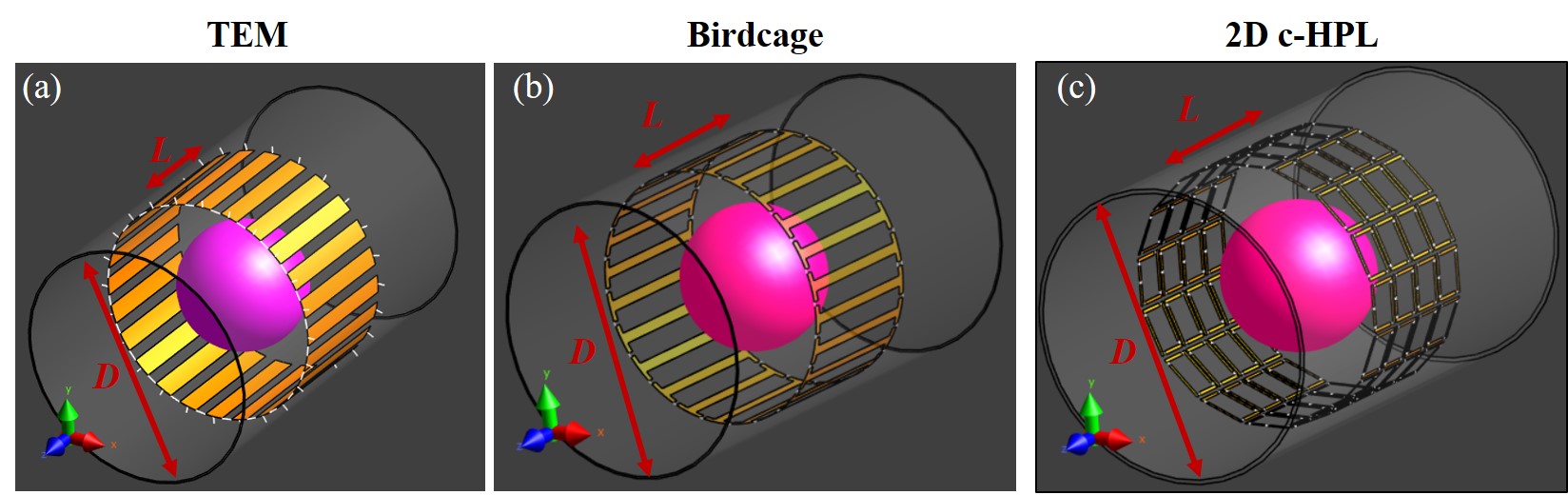
We used [16] to design and compare a 7T 2D c-HPL coil prototype to 24-rung TEM and birdcage coils when loaded with a spherical phantom (diameter=340 mm, εr=78, σ=0.46 S/m) (Figure-1). All coils have the same dimensions [8] (diameter=60 cm, length=33 cm, shield diameter=66 cm, and shield length=1 m). Decoupling and tuning capacitors of 5 pF and 2.5 pF, respectively were used for the TEM coil, while the birdcage coil used tuning capacitors of 4.9 pF.The 2D c-HPL coil [9,17] was designed with 64 elements (i.e., 4 rows with 16 elements each). Elements were separated by 5 mm in the z-direction). Unit elements had a side length of 80 and 110 mm in the z and transverse directions, respectively. A copper strip width of 12.5 mm was used to construct conducting traces. Four capacitors with 8.25 pF capacitance were placed at the corners of each element to tune the imaging frequency to 298 MHz.
Mean absolute deviation (MAD) of the normalized B1+ distribution was calculated for a diameter-of-spherical-volume (DSV) of 35 cm to compare B1+ non-uniformities for the three coils. Peak spatial-average SAR maps [18] and SAR efficiencies at isocenter were calculated. Finally, a realistic body model, Ella [16] was used to obtain in silico B1+ and SAR maps for the given coils.
Results
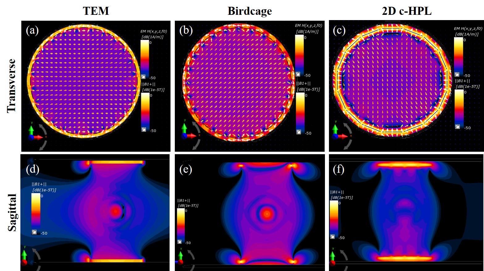
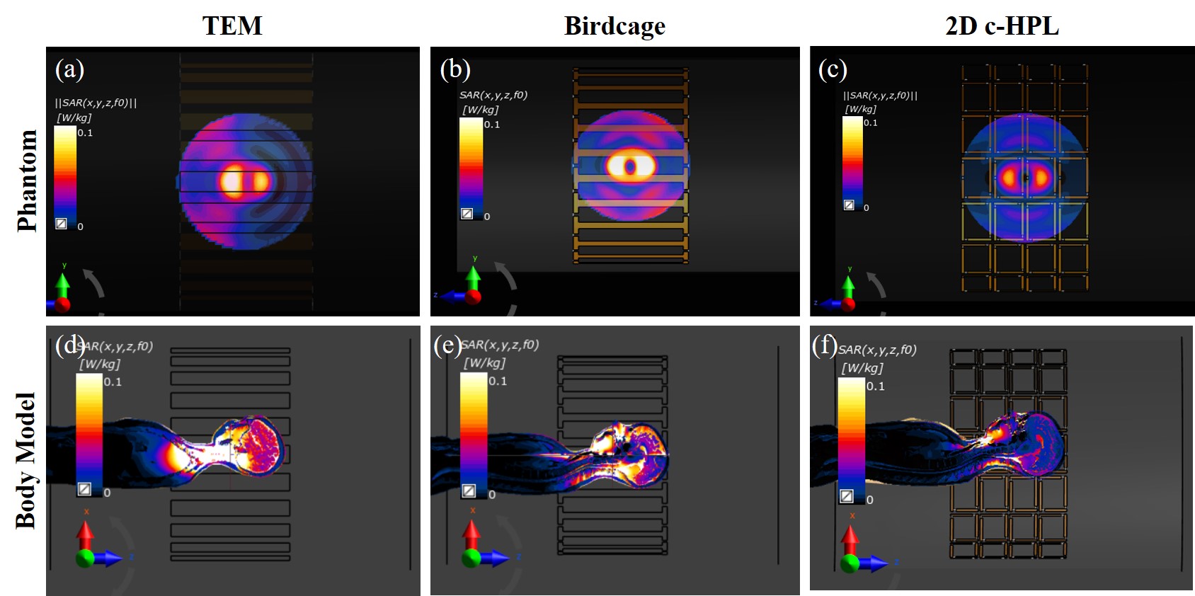
Figure 2 shows B1+ maps of TEM, birdcage, and 2D c-HPL coils for unloaded and loaded cases. The axial plane maps showed that the B1+ distributions of the coils are homogeneous in the unloaded case. Loading introduces inhomogeneity as expected (e.g., center brightening effect [19], Figure 2.e). The TEM coil showed significant unilateral wave propagation toward the inferior of the coil (Figure 2.d), while birdcage and 2D c-HPL coils exhibited symmetric, resonant, field distribution with higher B1+ amplitudes at the center of the phantom). 2D c-HPL coil showed lowered center brightening (1.7 μT for 2D c-HPL and 2.2 μT for birdcage) and lowered non-uniformity(15.9% compared to 18.1% for birdcage and 17.0% for TEM).Figure 3 depicts the in silico SAR results in comparison with the phantom results. SAR maps appear coincident with the B1+ maps with higher SAR deposition for the TEM coil unilaterally toward the inferior of the coil (Figure 3.a and 3.d) and for the birdcage coil at the center (Figure 3.b and 3.e). The 2D c-HPL coil results in lower SAR deposition, symmetrically centered at the origin (Figure 3.c).
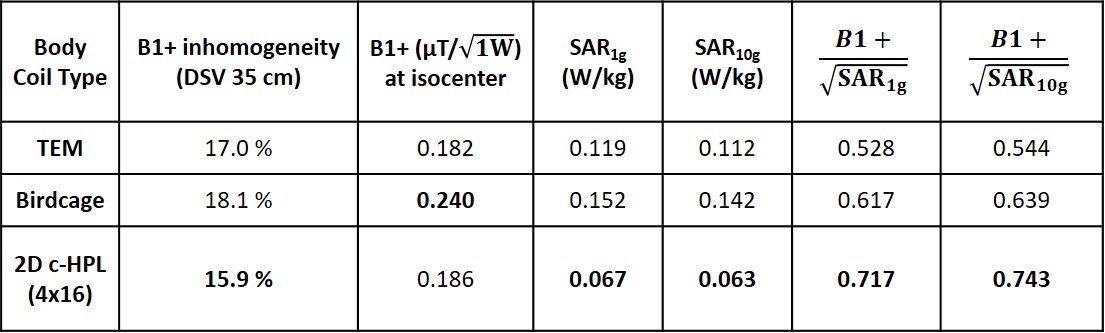
Table-1 compares the B1+ uniformity and SAR metrics for TEM, birdcage, and 2D c-HPL coils with an input RF power normalized to 1W. We observe a SAR efficiency improvement of 37% compared to the TEM coil and 16% compared to the birdcage coil.
Conclusion
A new 2D RF coil architecture is proposed and highlighted in comparison with same-size TEM and birdcage architectures for use in UHF MRI applications. Unlike decoupled coils, this architecture uses inductive coupling to create an imaging mode with better B1+ distribution and lower SAR deposition. We believe that this technology promises a pathway toward volumetric body coil designs for UHF in order to create the same clinical experience that physicians are used to at 3T. Beyond these intrinsic advantages, the 2D design also allows for long coil designs [17] as well as the flexibility to add or remove elements due to inductive connection.Acknowledgements
This work was supported in part by the National Institute of Health (NIH) through R00EB024341. The authors are also grateful to GE Healthcare for the equipment support.References
[1] A. G. Van Der Kolk, J. Hendrikse, J. J. M. Zwanenburg, F. Visser, and P. R. Luijten, "Clinical applications of 7T MRI in the brain," European Journal of Radiology, vol. 82, no. 5, pp. 708-718, 2013, doi: 10.1016/j.ejrad.2011.07.007.
[2] E. Springer et al., "Comparison of Routine Brain Imaging at 3 T and 7 T:," (in en), Investigative Radiology, vol. 51, no. 8, pp. 469-482, 08/2016 2016, doi: 10.1097/RLI.0000000000000256.
[3] E. F. McKiernan and J. T. O’Brien, "7T MRI for neurodegenerative dementias in vivo: a systematic review of the literature," J Neurol Neurosurg Psychiatry, vol. 88, no. 7, pp. 564-574, 2017.
[4] M. A. Erturk, X. Li, P.-F. Van de Moortele, K. Ugurbil, and G. J. Metzger, "Evolution of UHF body imaging in the human torso at 7T: technology, applications, and future directions," Topics in Magnetic Resonance Imaging, vol. 28, no. 3, p. 101, 2019.
[5] O. Kraff and H. H. Quick, "7T: Physics, safety, and potential clinical applications," (in en), Journal of Magnetic Resonance Imaging, vol. 46, no. 6, pp. 1573-1589, 2017 2017, doi: 10.1002/jmri.25723.
[6] T. M. Fiedler, M. E. Ladd, and A. K. Bitz, "SAR Simulations & Safety," (in en), NeuroImage, vol. 168, pp. 33-58, March 1, 2018 2018, doi: 10.1016/j.neuroimage.2017.03.035.
[7] A. Sadeghi‐Tarakameh et al., "In vivo human head MRI at 10.5T: A radiofrequency safety study and preliminary imaging results," Magnetic Resonance in Medicine, vol. 84, no. 1, pp. 484-496, 2020, doi: 10.1002/mrm.28093.
[8] J. T. Vaughan et al., "Whole-body imaging at 7T: Preliminary results," (in en), Magnetic Resonance in Medicine, vol. 61, no. 1, pp. 244-248, 2009 2009, doi: 10.1002/mrm.21751. [9] H. U. Voss and D. J. Ballon, "High-pass two-dimensional ladder network resonators for magnetic resonance imaging," IEEE Trans Biomed Eng, vol. 53, no. 12 Pt 2, pp. 2590-3, Dec 2006, doi: 10.1109/TBME.2006.880870.
[10] E. Kazemivalipour, A. Sadeghi‐Tarakameh, and E. Atalar, "Eigenmode analysis of the scattering matrix for the design of MRI transmit array coils," Magnetic Resonance in Medicine, 2020, doi: 10.1002/mrm.28533.
[11] M. A. Erturk, A. J. Raaijmakers, G. Adriany, K. Ugurbil, and G. J. Metzger, "A 16-channel combined loop-dipole transceiver array for 7 Tesla body MRI," Magn Reson Med, vol. 77, no. 2, pp. 884-894, Feb 2017, doi: 10.1002/mrm.26153.
[12] N. I. Avdievich, G. Solomakha, L. Ruhm, K. Scheffler, and A. Henning, "Evaluation of short folded dipole antennas as receive elements of ultra‐high‐field human head array," Magnetic Resonance in Medicine, vol. 82, no. 2, pp. 811-824, 2019, doi: 10.1002/mrm.27754.
[13] N. I. Avdievich, G. Solomakha, L. Ruhm, J. Bause, K. Scheffler, and A. Henning, "Bent folded‐end dipole head array for ultrahigh‐field MRI turns “dielectric resonance” from an enemy to a friend," Magnetic Resonance in Medicine, vol. 84, no. 6, pp. 3453-3467, 2020, doi: 10.1002/mrm.28336.
[14] A. A. Hurshkainen et al., "A parametric study of radiative dipole body array coil for 7 Tesla MRI," (in en), Photonics and Nanostructures - Fundamentals and Applications, vol. 39, p. 100764, May 1, 2020 2020, doi: 10.1016/j.photonics.2019.100764.
[15] IT'IS Foundation, Sim4Life ver. 6.0, Zurich, Switzerland, 2020. [Online]. Available: https://zmt.swiss/sim4life/
[16] S. Gokyar, H. U. Voss, V. Taracila, F. Robb, D. J. Ballon, and S. A. Winkler, "An Electrically Long Ultra-High Field MRI Volume Body Coil Design," 2020, Dec, 15 Submitted to ISMRM.
[17] S. Gokyar et al., "A 2D High-Pass Ladder RF Coil Architecture for UHF MRI," 2020, Dec, 15, Submitted to ISMRM.
[18] IEC 60601-2-33. Medical Electrical Equipment – Part 2-33: Particular Requirements for the Basic Safety and Essential Performance of Magnetic Resonance Equipment for Medical Diagnosis, Edition 3.1, I. E. Commission, Geneva, 2013.
[19] V. Alagappan, "RF coil technology for parallel excitation and reception in high field MRI," Tufts University, 2008.
Figures