1579
A 28-channel decoupled Tic-Tac-Toe transmit radiofrequency coil for 7T MRI1University of Pittsburgh, Pittsburgh, PA, United States
Synopsis
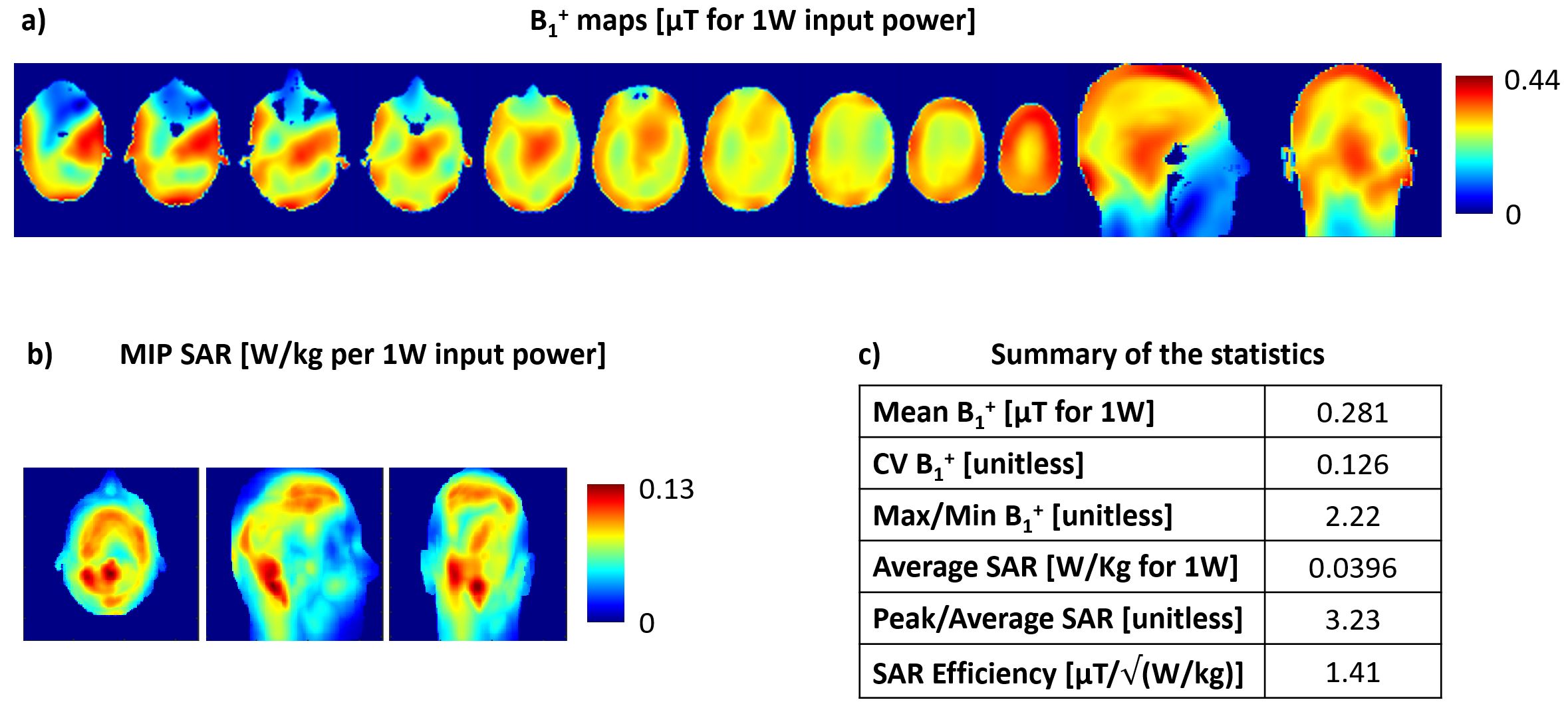
In this work, we investigated the potential of the smaller sizes of the Tic-Tac-Toe transmit coil elements, comparing the newly developed uncoupled configuration with the traditional coupled version of this RF coil design. Simulations with 14 Tic-Tac-Toe panels showed excellent levels of transmit field homogeneity at 7T (coefficient of variation = 12.6%, average = 0.28µT for 1W) while maintaining low levels of SAR (SAR efficiency = 1.41 µT/√(W/Kg)). The simulations were validated with phantom experiments. Future work includes the assembling of the 28-channel transmit coil and the investigation of the optimal power splitting strategy.
Introduction
The coupled 16-channel 9-inch (229x229mm2) Tic-Tac-Toe (TTT) head coil has shown highly homogenous circularly polarized transmit RF magnetic field (B1+) and low levels of SAR at 7T [1-3]. In order to further improve the RF performance, patient comfort, and accessibility, the coil panel design can be reduced to approximately a quarter of its original area, increasing the number of transmit channels and, therefore, increasing the degrees of freedom in RF shimming optimizations. The smaller design also permits the coil to be completely open from the front.However, the coupling of the TTT coil greatly increases in the smaller sizes, reducing the power efficiency and potentially impacting the B1+ homogeneity in systems with limited power capabilities. In this work, we present an alternative uncoupled design of the TTT design by removing the opposite ports from the traditional design and inserting a matching circuit. Simulations of the full 28-channel model and experimental validation using a single panel and a spherical phantom are presented.
Methods
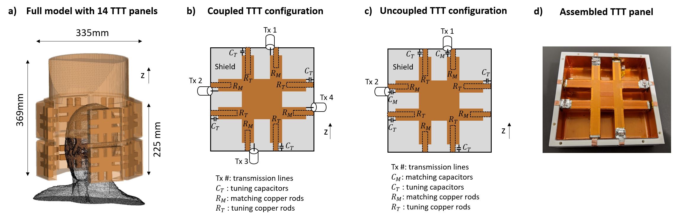
The computational models were created with 1.58 mm isotropic Yee cells utilizing an in-house developed software written in Python3 language. Figure 1a shows the full model, which has 14 TTT panels around the head (Duke model) and an aperture in the frontal portion for improved subject comfort and for easy access to projection in fMRI studies. Two different configurations of the panels are presented: a coupled TTT design with 4 channels per panel (Figure 1b), and an uncoupled TTT design with 2 channels (Figure 1c). One implemented TTT panel is shown in Figure 1d. The full model utilizes the 2 channels per panel configuration, totaling 28 channels. A proof-of-concept model was 3D printed in ABS plastic for the surrounding box and the struts were CNC machined from Rexolite sheets. Double side 4µm-thick copper sheets (Polyflon, Germany) were used for the shields and 8µm-thick copper sheets were used for the struts.The RF fields were simulated using an in-house developed code, written in C language. Phase and amplitude RF-shimming was performed using MATLAB R2020a, with a combination of B1+ CV, B1+ max/min, and average SAR as the cost function, constraining the average B1+ to greater than 0.27μT for 1W input power, following the strategy described in [1]. The region of interest in the optimization includes: 1) for the B1+ fields, the head from the bottom of the brain stem to the top of the head, excluding the nasal cavities and ears; 2) for the electrical RF fields, the whole head from the top of the neck. Experimental B1+ maps were collected at 7T (Magnetom, Siemens, Germany) using the turbo flash sequence, with the following parameters: TR/TE = 2000/1.16 ms; flip angle from 0° to 90° in 18 degrees increments; acquisition time = 12 min; resolution 3.2 mm isotropic. A spherical phantom with 169 mm in diameter, relative permittivity of 79, and conductivity of 0.49 S/m was used in the experimental validation.
Results
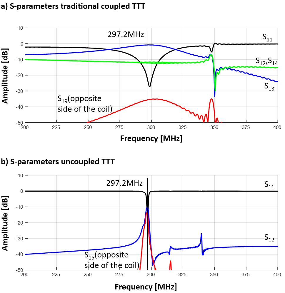
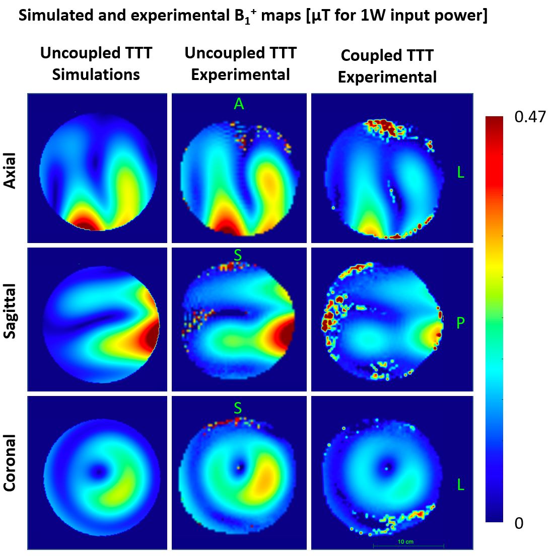
Figures 2a and 2b show the simulated s-parameters of the two configurations tuned and matched to 297.2 MHz. The coupled TTT presents a strong coupling between the opposite ports of the panel (-0.82dB) and low coupling between ports on opposite sides of the coil (-36dB), while the uncoupled configuration presents similar coupling between the adjacent port (-12dB) and the port located in the opposite side of the coil (-12dB). Figure 3 shows the B1+ and SAR performance of the 28-channel uncoupled model, achieving whole-brain homogenous B1+ field distribution while maintaining low levels of power deposition in the tissues. Figure 4 shows the comparison between the simulated single panel B1+ maps and the experimental data.Discussion
The uncoupled 2-channel TTT coil design has shown higher power efficiency in comparison with the traditional 4-channel configuration, which can be translated into high homogeneity while maintaining high levels of SAR efficiency with RF-shimming of the 28-channel coil. We expect, however, the 4-channel and 2-channel to present similar performance with high capability power amplifiers (16 kW or more for instance). The potential disadvantage of the uncoupled configuration is the higher sensitivity to load, this issue will be further investigated in future work.Future work includes the development of methods to split the power to the channels. Ideally, we want to use the single-channel mode from the MRI scanner and split the power as close as possible from the results from the RF-shimming optimization. Moreover, while only one RF-shimming case is presented in this work, there is an infinite number of operational points that can be used to drive the transmit channels, which represents a tradeoff between homogeneity, SAR efficiency, and B1+ power efficiency.
Acknowledgements
This work was supported by NIH R01MH111265 and R01AG063525. The author Tales Santini was partially supported by the CAPES Foundation, Ministry of Education of Brazil, 13385/13-5. This research was also supported in part by the University of Pittsburgh Center for Research Computing (CRC) through the resources provided.References
1. Santini T, Wood S, Krishnamurthy N, Martins T, Aizenstein HJ, Ibrahim TS. Improved 7 Tesla Transmit Field Homogeneity with Reduced Electromagnetic Power Deposition Using Coupled Tic Tac Toe Antennas. bioRxiv. 2020:2020.11.06.371328. doi: 10.1101/2020.11.06.371328. Accepted for publication in Scientific Reports.
2. Krishnamurthy N, Santini T, Wood S, Kim J, Zhao T, Aizenstein HJ, et al. Computational and experimental evaluation of the Tic-Tac-Toe RF coil for 7 Tesla MRI. PloS one. 2019;14(1):e0209663. Epub 2019/01/11. doi: 10.1371/journal.pone.0209663. PubMed PMID: 30629618.
3. Santini T, Zhao Y, Wood S, Krishnamurthy N, Kim J, Farhat N, et al. In-vivo and numerical analysis of the eigenmodes produced by a multi-level Tic-Tac-Toe head transmit array for 7 Tesla MRI. PloS one. 2018;13(11):e0206127. doi: 10.1371/journal.pone.0206127.
Figures