1578
Design of a 19-Channel hybrid array system for Foot/Ankle Imaging at 7T
Aditya Ashok Bhosale1, Leslie L Ying1, and Xiaoliang Zhang1
1Biomedical Engineering, University at Buffalo, Buffalo, NY, United States
1Biomedical Engineering, University at Buffalo, Buffalo, NY, United States
Synopsis
Microstrips are being used in MR applications due to their unique properties such as reduced radiation loss, high frequency capability, and reduced perturbation of sample loading to the RF coil compared to conventional coils. In this study, we propose a 19-channel hybrid array consisting of 14 Microstrips and 5 loop coils placed on the foot/ankle phantom to cover maximum area of the subject at 7T.
introduction
Microstrips are promising in high-frequency RF coil designs for MR applications at ultrahigh fields due to their unique advantages in high-frequency range over conventional coils. Microstrips are purely distributed and consist of a thin strip conductor which can be silver or copper. Microstrip has a ground plane which is separated from the strip conductor by a low-loss dielectric material with a certain thickness. Microstrips provide higher Q-factor and excellent decoupling performance, require no shielding, have lower costs, and are easy to fabricate 1. Taking the advantages into consideration, we propose a hybrid array of microstrips and surface coils acting together to provide better B1 field distribution for imaging geometrically irregular Foot/Ankle anatomy at the ultrahigh field of 7T.Method
The hybrid array consists of 14 microstrips and 5 surface coils placed closely on a foot/ankle phantom. The strip conductor has a width of 3mm and a length of 18 cm. The setup is as shown in fig.1. The strip conductor is placed directly on the Teflon substrate with 3mm thickness and 10 mm width. We have assigned an external boundary of the substrate as the ground plane. 8 Microstrips form a circular array and are placed around the ankle region. 6 microstrips form one planar array and are placed over the metatarsal bones of the foot. 5 surface coil channels cover the foot region from sides and cover the area not covered by the microstrip arrays. The two surface coil channels on the heel region of the foot model are 8×10 cm2. The circular array is excited by the current value of 1[A] with every microstrip is 450 out of phase from neighboring microstrips. Other channels were excited by 1[A] current. The input power was kept as 1 watt for each channel. We added termination capacitors of 1[pF] on both sides of the microstrips to tune all the channels to 300 MHz (7T), we also added a capacitor of 1[pF] on surface coils to tune them at 300 MHz. The material properties for foot/ankle phantom were as follows: relative permittivity = 50, relative permeability = 1, electrical conductivity = 0.08 s/m. The substrate used for the microstrip had the following material properties: relative permeability = 1, relative permittivity = 2.1, electrical conductivity = 0 s/m. We assigned copper material to the surface coils and strip conductors. We performed simulations where all the channels were excited and were working together and evaluated the B1+ fields and electric fields produced by them. B1+field distribution along the transverse plane of the phantom were reconstructed and analyzed.Result
The simulation results of the 19-Channel hybrid array system for foot/ankle imaging at 7T,300 MHz are obtained as shown in fig.2,3.Discussion/Conclusion
The 19-Channel hybrid array system consisting of microstrips and surface coils was designed for foot/ankle imaging at 7T. We were able to generate B1 fields with concentration at the site of interest. The Heel region and the Metatarsal region had more concentrated B1 fields. Changes in the array structure and further modifications may improve the performance of this multichannel coil array system.Acknowledgements
No acknowledgement found.References
1. Zhang X, Ugurbil K, Chen W. Microstrip RF surface coil design for extremely high-field MRI and spectroscopy. Magn Reson Med. 2001 Sep;46(3):443-50. doi: 10.1002/mrm.1212. PMID: 11550234Figures
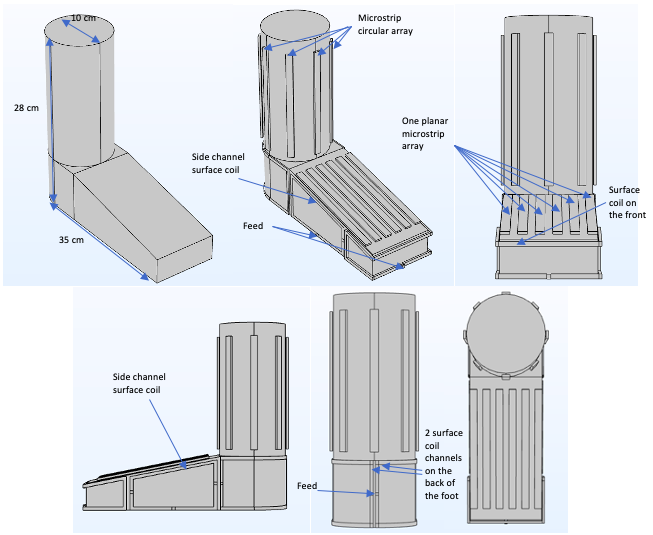
Fig.1. Simulation model showing the 19-channel hybrid array system a)Foot/Ankle phantom b)3D view of the phantom with RF coil system c) Front View of the system d) Side view of the system e) Back view of the system f) Top view of the system.
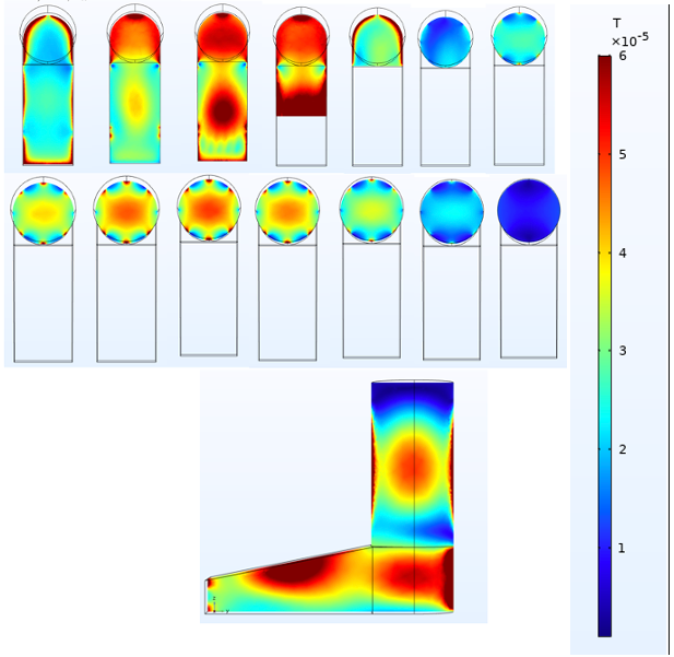
Fig.2. B1+ field distribution along the transverse plane of the phantom. The transverse plane propagates from lower dimensions to higher dimensions. B) B1+ field distribution along the sagittal plane of the phantom at the center.
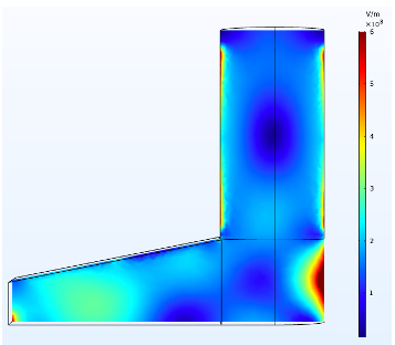
Fig.3. Electric field distribution along the sagittal plane of the phantom at the center.