1577
Development of a Dedicated Mono-surface 16-Element Transceiver Dipole Antenna Array for Parallel Transmission Cardiac MRI in Pigs at 7 Tesla
Ibrahim A. Elabyad1, Maxim Terekhov1, Michael Hock1, David Lohr1, and Laura M. Schreiber1
1Chair of Molecular and Cellular Imaging, Comprehensive Heart Failure Center (CHFC), University Hospital Wuerzburg, Wuerzburg, Germany
1Chair of Molecular and Cellular Imaging, Comprehensive Heart Failure Center (CHFC), University Hospital Wuerzburg, Wuerzburg, Germany
Synopsis
To improve parallel imaging performance for cardiac MRI in pigs at 7T, a dedicated transceiver 16-element antisymmetric dipole antenna array was developed and tested. EMF-simulations were performed with the antisymmetric dipole array loaded with a dedicated pig thorax-shaped phantom. Imaging performance of the dipole array was validated through MR-measurements in a pig phantom and an 85kg pig cadaver. The dipole array demonstrated a threefold improvement in coefficient-of-variation of the measured FA maps after $$${B_1^+}$$$-shimming using the vendor integrated pTx-platform. Parallel imaging with acceleration factor up to R=4 was possible while maintaining a mean g-factor of 1.13 within the pig heart.
Introduction
Different types of radio-frequency (RF) coil arrays have allowed significant progress for body-imaging at UHF (e.g., local Tx/Rx loops1–4, dipoles5–10, and combined dipoles/loops11–12). Dipole antennas have become popular transmit elements for body-imaging at UHF because dipoles generate symmetric and relatively uniform transmit $$${B_1^+}$$$-field distribution with sufficient penetration depth into deep-seated organs, such as the heart, compared to traditional loops. However, the size of a standard dipole antenna should be substantially shorter than the half-wavelength of the RF-frequency in free-space to accommodate the human thorax size (e.g., 30cm along z-axis). These relatively long dipole dimensions impose many constraints for the design of double-row transceiver antenna arrays to enable parallel imaging acceleration in double oblique slices for cMRI at 7T. It is widely accepted from practical experience that a standard dipole array with straight elements should be separated with a decoupling gap of 8cm to keep the decoupling coefficient $$$S_{21}$$$=−12dB. Furthermore, the prominent characteristics of a straight dipole array are a continuous and relatively homogeneous $$${B_1^+}$$$-profile along the element direction (z-axis). The efficient parallel imaging acceleration in double-oblique slices in cMRI using standard dipole array for receiving is only possible in the left-right (L−R) direction. Therefore, we propose a dedicated antisymmetric 16-element dipole array that allows for the shaping of the overall $$${B_1^+}$$$-field in all three spatial directions based on the superposition of the individual $$${B_1^+}$$$-profiles of all 16-elements.Methods
Before constructing the dipole antenna array, inter-element decoupling gap distances (D1 and D2) were optimized numerically using CST-Microwave-Studio (CST-MWS) [Figure 1(a)&(b)]. EMF-simulations were carried out for the 16-element antisymmetric dipole array using CST-MWS [Figure 2(a)]. All dipoles have a copper (Cu) track width of 10mm and a thickness of 35µm etched on a 0.3mm FR4-printed-circuit-board (PCB). The total external dimension of the array is 26.5×60.4cm2. The PCB was bent around a half-elliptical shape housing. For the phantom measurements, the array was loaded by a dedicated pig thorax-shaped phantom ($$$\epsilon_{r}$$$=59.3 and $$$\sigma$$$=0.79S/m) positioned at a 2.5cm distance from the top array surface as published in13 [Figure 2(b)]. RF-circuit co-simulation was employed in CST-DS for optimal matching/tuning and to get an initial guess for the optimal lumped elements14. Dipoles were tuned to 297.2MHz using two series inductors and matched to better than −14dB using a lattice balun network. Figure 2(c)&(d) shows the prototypes of the pig phantom and the antisymmetric dipole array. The coefficient-of-variation ($$$CoV)=\frac{std(B_1^+)}{mean(B_1^+)}$$$.Results and Discussion
Figure 1(c)&(d) shows the simulated S-parameters for the 4-element straight dipoles and antisymmetric dipole design as a function of D1. The decoupling coefficient $$$S_{21}$$$ decreases monotonically with increasing the decoupling gap distance D1 for the straight dipoles (e.g. with D1=80mm, $$$S_{21}$$$=13dB). For the 4-element antisymmetric dipole, the minimum transmission coefficients ($$$S_{21}$$$=15.31dB and $$$S_{31}$$$=18.12dB) occurred at distances of D1 between 55mm and 60mm with D2=10mm to keep accepted decoupling between the straight and L-shaped dipoles ($$$S_{31}$$$ varies from −10dB to −13dB). Optimal gap distances of D1=55mm and D2=10mm were chosen. The antisymmetric dipole design has essentially improved $$${B_1^+}$$$-penetration and full coverage along the z-axis [Figure 1(e)&(f)]. For larger imaging FOV, up to 40% of perimeter distance in the L−R direction can be saved while accommodating 16-element dipoles with the same outer size as an 8-element array of straight dipoles. Figure 3(a)-(d) demonstrates the measured FA-maps of a central transversal slice in the pig thorax-shaped phantom before and after $$${B_1^+}$$$-shimming acquired using the dipole antenna array and with the vendor-integrated pTx $$${B_1^+}$$$-shimming platform. Three different ROIs (120x183x20mm3, 135x230x50mm3, and 100x120x50mm3) were tested for Shim1, Shim2, and Shim3, respectively. The CoV values were 0.29, 0.21, 0.13, and 0.10, for implemented phases (before $$${B_1^+}$$$-shimming), Shim1, Shim2, and Shim3, respectively. This result shows that after pTx-shimming, the CoV was improved by factors >1.40, 2.20, and 2.90, for Shim1, Shim2, and Shim3, respectively, compared to the values before pTx-shimming. Ex-vivo SNR-maps of the dipole array within the region of the heart were shown in Figure 4. Figure 4(a) shows the SNR-map reconstructed using the vendor’s “Adaptive Combine” method which is based on the optimally weighted combination of the individual Rx-elements sensitivity profiles. The bottom panel shows the ratio of the optimized and root-sum-of-square (RSS) combination of Rx-elements. One can observe a strong variation of SNR ratio from 0.5 in anterior to 2 in posterior, reflecting increased receive contribution of the side elements compared to the top elements mainly contributing to the anterior wall. Figure 4(b) shows g-factor maps for mid-myocardial and apical slices in the top and bottom rows, respectively. The maps demonstrate relatively homogeneous g-factor distributions up to an acceleration factor R=4 when phase encoding (PE)-direction is in the L−R direction. The ratio of maximal and mean g-factor is consistently below two. Figure 5 shows high-resolution late-gadolinium-enhancement (LGE) MR-images acquired post-mortem in an animal after induction of myocardial infarction. The scar tissue which is hyperintense because of increased gadolinium content can be observed in the septal and anterior walls.Conclusion
A 16-element antisymmetric transceiver dipole antenna array was developed aiming for improved static phase $$${B_1^+}$$$-shimming and parallel imaging capabilities for cMRI at 7T. The new 16-element antisymmetric dipole array provided additional degrees-of-freedom for adjustment of $$${B_1^+}$$$-field in xz-plane (parallel to the dipole elements) compared to traditional design.Acknowledgements
This project is funded by the Federal Ministry of Education and Research (BMBF), Grant/Award Number: 01EO1004 & 01EO1504. We thank Maya Bille and Florian Schnitter for the help in the animal experiments.References
- A. Graessl et al., Modular 32-channel transceiver coil array for cardiac MRI at 7.0T, Magn. Reson. Med. 72 (1) (2014) 276–290.
- M.A. Dieringer et al., Design and application of a four-channel transmit/receive surface coil for functional cardiac imaging at 7T, J. Magn. Reson. Imag. 33 (3)(2011) 736–741.
- A. Gräßl et al., Design, evaluation and application of an eight channel transmit/receive coil array for cardiac MRI at 7.0T, Eur. J. Radiol. 82 (5) (2013) 752–759.
- C. Thalhammer et al., Two-dimensional sixteen channel transmit/receive coil array for cardiac MRI at 7.0 T: design, evaluation, and application, J. Magn Reson Imag. 36 (4) (2012) 847–857.
- Raaijmakers AJ, Ipek O, Klomp DW, Possanzini C, Harvey PR, Lagendijk JJ, van den Berg CA. Design of a radiative surface coil array element at 7 T: the single-side adapted dipole antenna. Magn Reson Med 2011;66:1488–1497.
- Raaijmakers AJ, Italiaander M, Voogt IJ, Luijten PR, Hoogduin JM, Klomp DW, van den Berg CA. The fractionated dipole antenna: a new antenna for body imaging at 7 Tesla. Magn Reson Med 2016;75: 1366–1374.
- Ipek O, Raaijmakers AJ, Klomp DW, Lagendijk JJ, Luijten PR, van den Berg CA. Characterization of transceive surface element designs for 7 tesla magnetic resonance imaging of the prostate: radiative antenna and microstrip. Phys Med Biol 2012;57:343–355.
- C. Oezerdem et al., 16-channel bow tie antenna transceiver array for cardiac MR at 7.0 tesla, Magn. Reson. Med. 75 (6) (2016) 2553–2565.
- A.J.E. Raaijmakers, P.R. Luijten, C.A. van Den Berg, Dipole antennas for ultrahigh-field body imaging: a comparison with loop coils, NMR Biomed. 29 (9) (2016) 1122–1130.
- M.A. Ertürk et al., Toward imaging the body at 10.5 tesla, Magn. Reson. Med. 77 (1) (2017) 434–443.
- M.A. Ertürk, A.J. Raaijmakers, G. Adriany, K. Ug˘urbil, G.J. Metzger, A 16-channel combined loop-dipole transceiver array for 7 Tesla body MRI, Magn. Reson. Med. 77 (2) (2017) 884–894.
- B.R. Steensma et al., An 8-channel Tx/Rx dipole array combined with 16 Rx loops for high-resolution functional cardiac imaging at 7 T, Magn Reson Mater Phy 31 (1) (2018) 7–18.
- Elabyad IA, Terekhov M, Lohr D, Stefanescu MR, Baltes S, Schreiber LM. A Novel Mono-surface Antisymmetric 8Tx/16Rx Coil Array for Parallel Transmit Cardiac MRI in Pigs at 7T. Scientific Reports. 2020;10(1):3117.
- M. Kozlov, R. Turner, Fast MRI coil analysis based on 3-D electromagnetic and RF circuit co-simulation, J. Magn Reson 200 (1) (2009) 147–152.
Figures
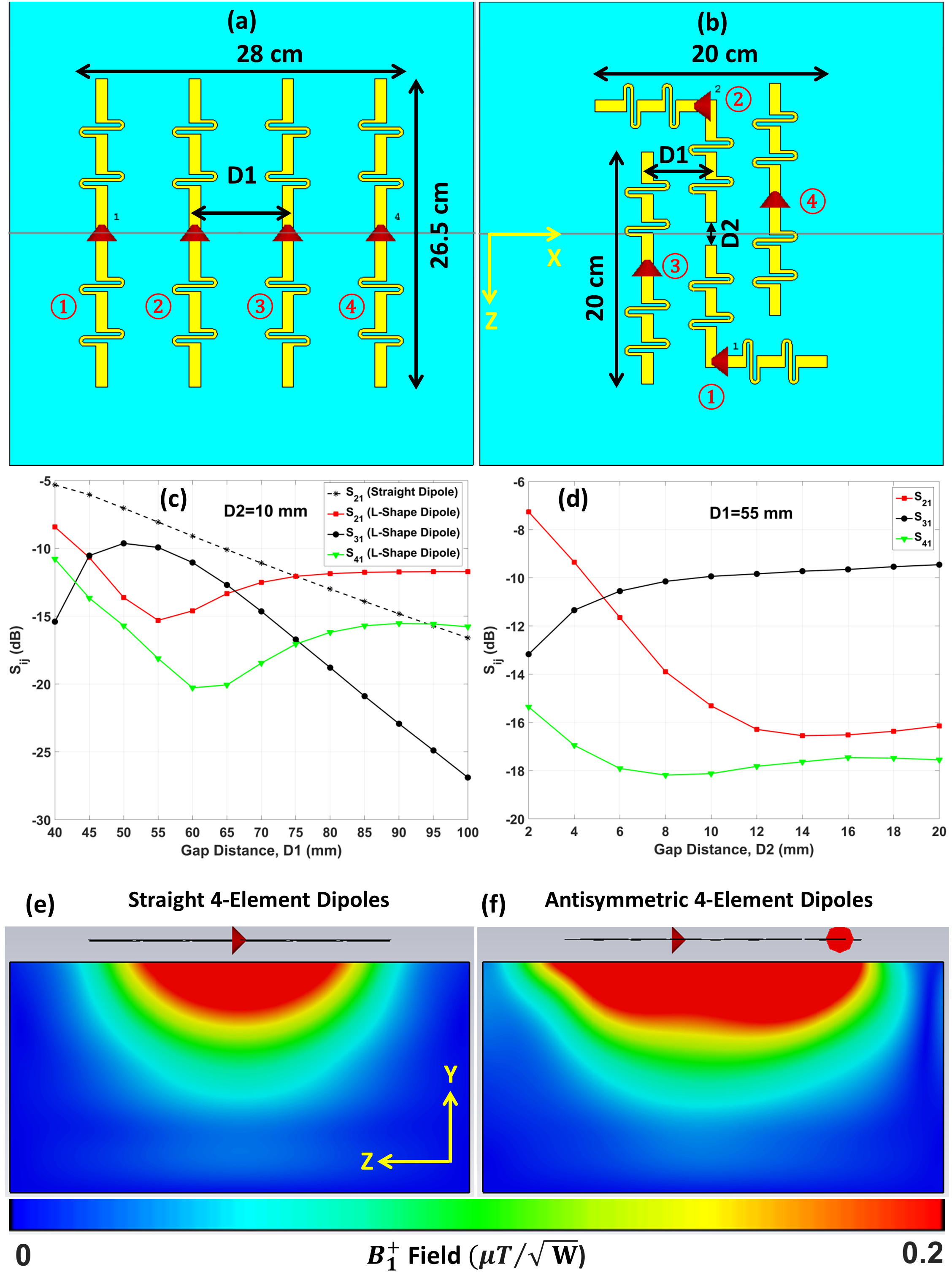
Figure 1. (a) RF simulation model for 4-element straight dipoles
with a center-to-center gap distance of D1=80mm. (b) 4-element antisymmetric dipoles. (c) Simulated S-parameters versus D1 for the standard straight dipoles and the antisymmetric dipoles at D2=10mm
placed on a rectangular uniform phantom with dimensions (40×40×20cm3).
(d) Simulated S-parameters in dB versus the vertical gap
distance (D2) for the antisymmetric dipoles at D1=55mm. Simulated
$$${B_1^+}$$$ field distribution in the central sagittal plane, for straight (e) and
antisymmetric dipoles (f).
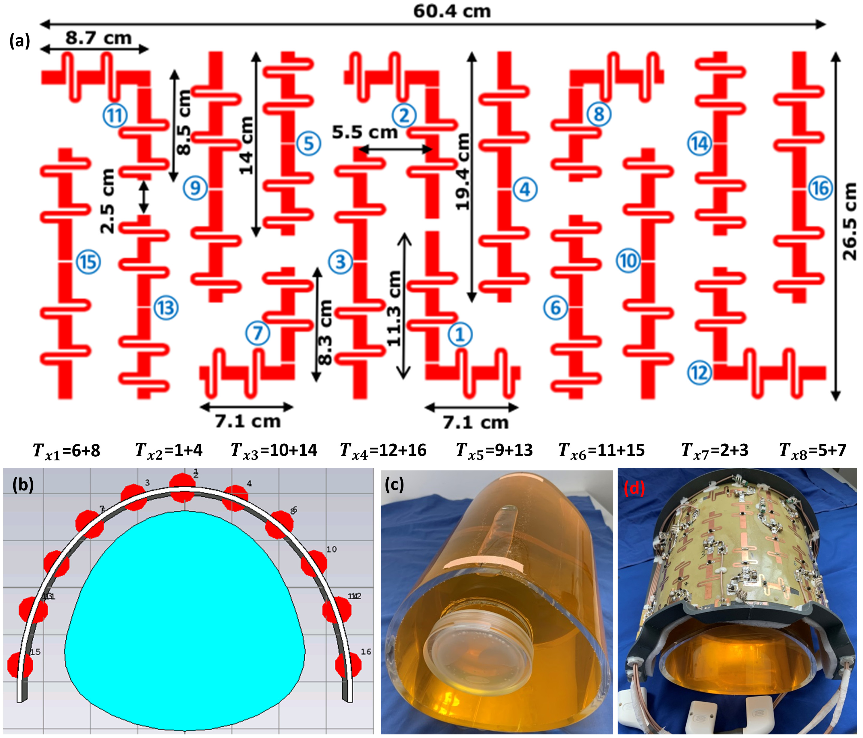
Figure 2. (a) Schematic
of the mono-surface antisymmetric 16-element dipole
antenna array with element dimensions,
paring channels, and channel numbers with every two neighboring dipoles to
form 8Tx-channels for the pTx system (8Tx/16Rx). (b)
RF simulation model as simulated in CST-MWS of the new dipole antenna array
loaded with a dedicated pig thorax phantom. (c)-(d)
Prototypes of the dedicated pig thorax phantom and the antisymmetric dipole antenna array.
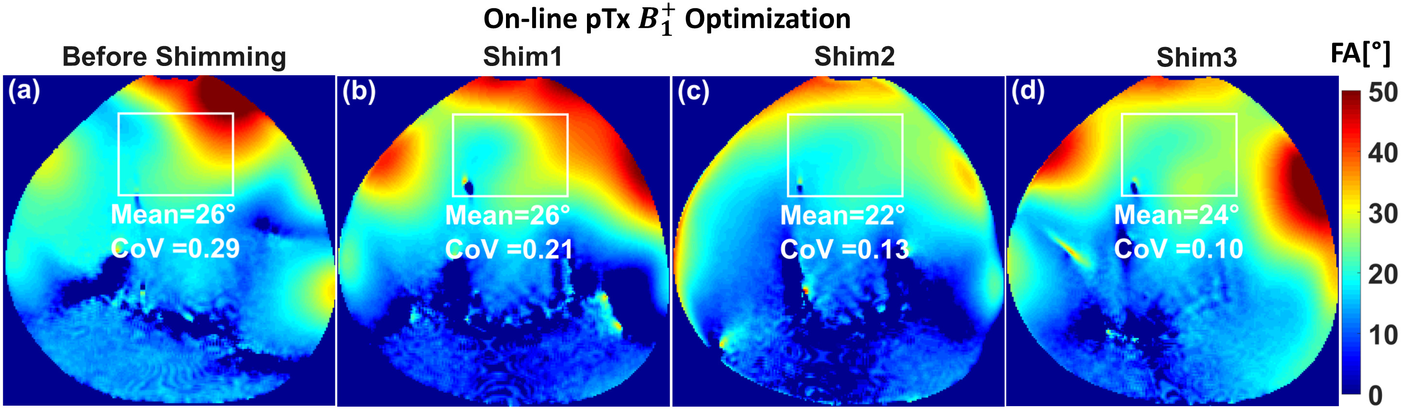
Figure 3. Measured combined central transversal FA-maps in
degrees acquired using the antisymmetric 8Tx/16Rx dipole antenna array before
on-line pTx-shimming with implemented phases (a) and
after pTx $$${B_1^+}$$$ shimming (b)-(d) within three
different 3D ROIs (120x183x20mm3, 135x230x50mm3, and
100x120x50mm3) for Shim1, Shim2, and Shim3, respectively.
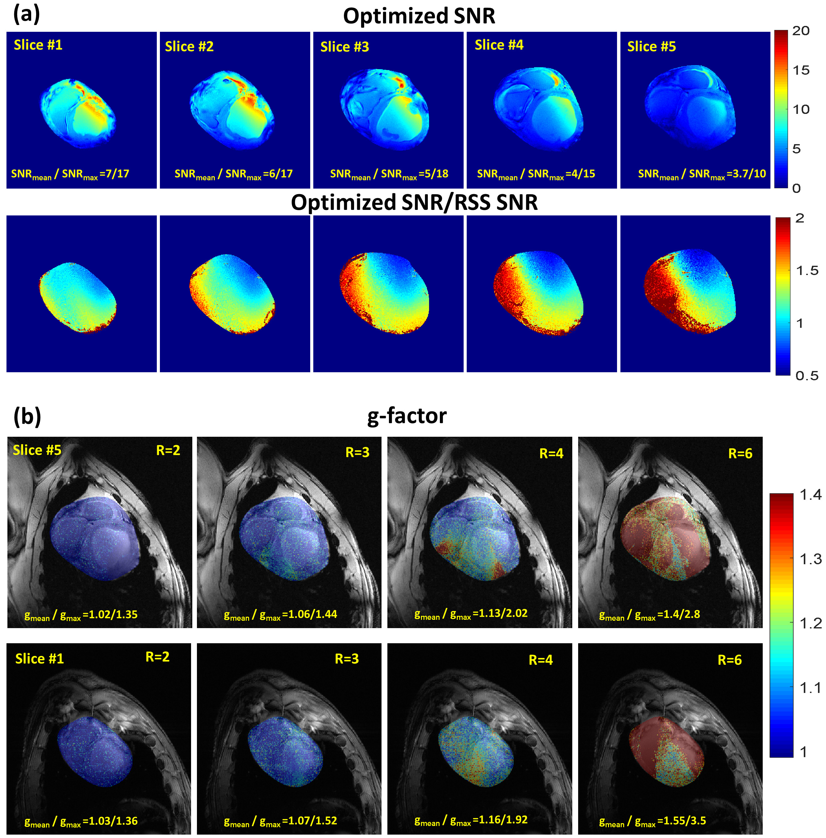
Figure 4. Ex-vivo SNR
map of the dipole array in the region of the heart for 5 slices. The top row
shows the optimized SNR of the array reconstructed using an adaptive combination
of individual elements images. The bottom row (a) shows the ratio of optimized SNR and
SNR map reconstructed using RSS of individual elements. (b) g-factor maps for two
slices overlaid with anatomical images. Reliable parallel imaging acceleration
with a factor up to R=4 is possible with the new array.
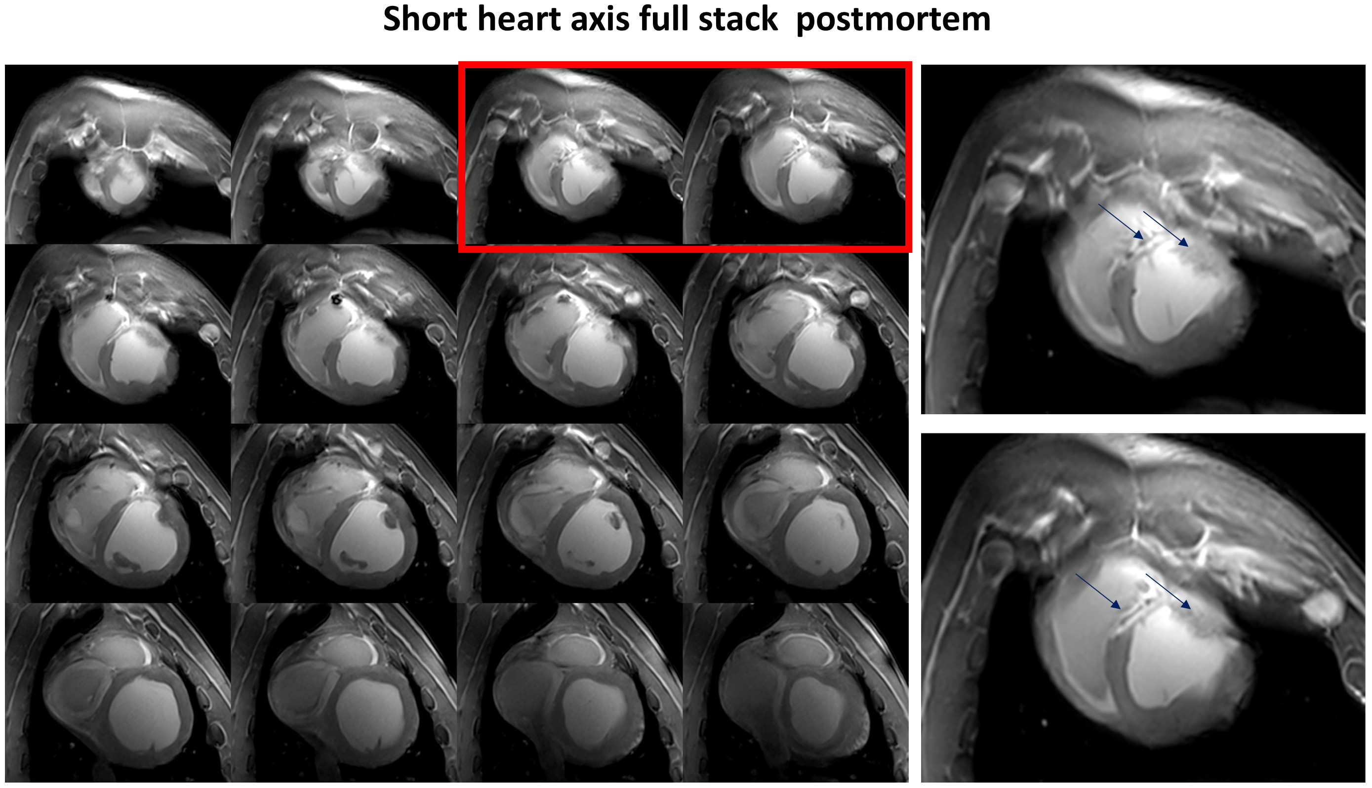
Figure 5. Slices of the short-axis
view stack of the pig heart acquired post-mortem. The right panels show
increased image slices marked red on the left panel. The LGE in the
post-infarction scar is observed in the septal and anterior wall (arrows).
Sufficient $$${B_1^+}$$$ field penetration and homogeneity without destructive interferences are
achieved in the whole heart in both anterior-posterior and basal-apical
directions.