1575
Effect on SAR and Transmit Efficiency by Geometrical Configuration of RF Transmit Head Coil for 7 T MRI1Electronic Engineering, Hanyang University, Seoul, Korea, Republic of
Synopsis
As the risk of RF heating in UHF MRI due to high specific absorption rate (SAR), recent work to design the coil focused to reduce SAR. In this study, the impact of the geometrical shape of the multi-channel RF head coil on the transmit efficiency (TE) and SAR efficiency (SE) was analyzed. Four different configurations of the head coil were simulated. it is evident from the results that a coil configuration similar to the head shape is required to optimize the TE and SE simultaneously.
Introduction
In the ultra-high field (UHF) MRI over 7 T, a multi-channel coil is used to alleviate the B1+ field inhomogeneity caused by the short wavelength of B1 signal. Early research on designing the multi-channel RF coil focused on improving the transmit efficiency so that adjustable coil or flexible coil placing the channels close to the target object to enhance the applied B1+ field was introduced [1,2]. However, as the risk of RF heating in UHF MRI due to high specific absorption rate (SAR), recent studies focused on designing the coil with low SAR [3,4]. In this study, the impact of the geometrical shape of the multi-channel RF head coil on the transmit efficiency and SAR to provide a guidance to design a RF head coil optimizing its performance for various head shapes.Methods
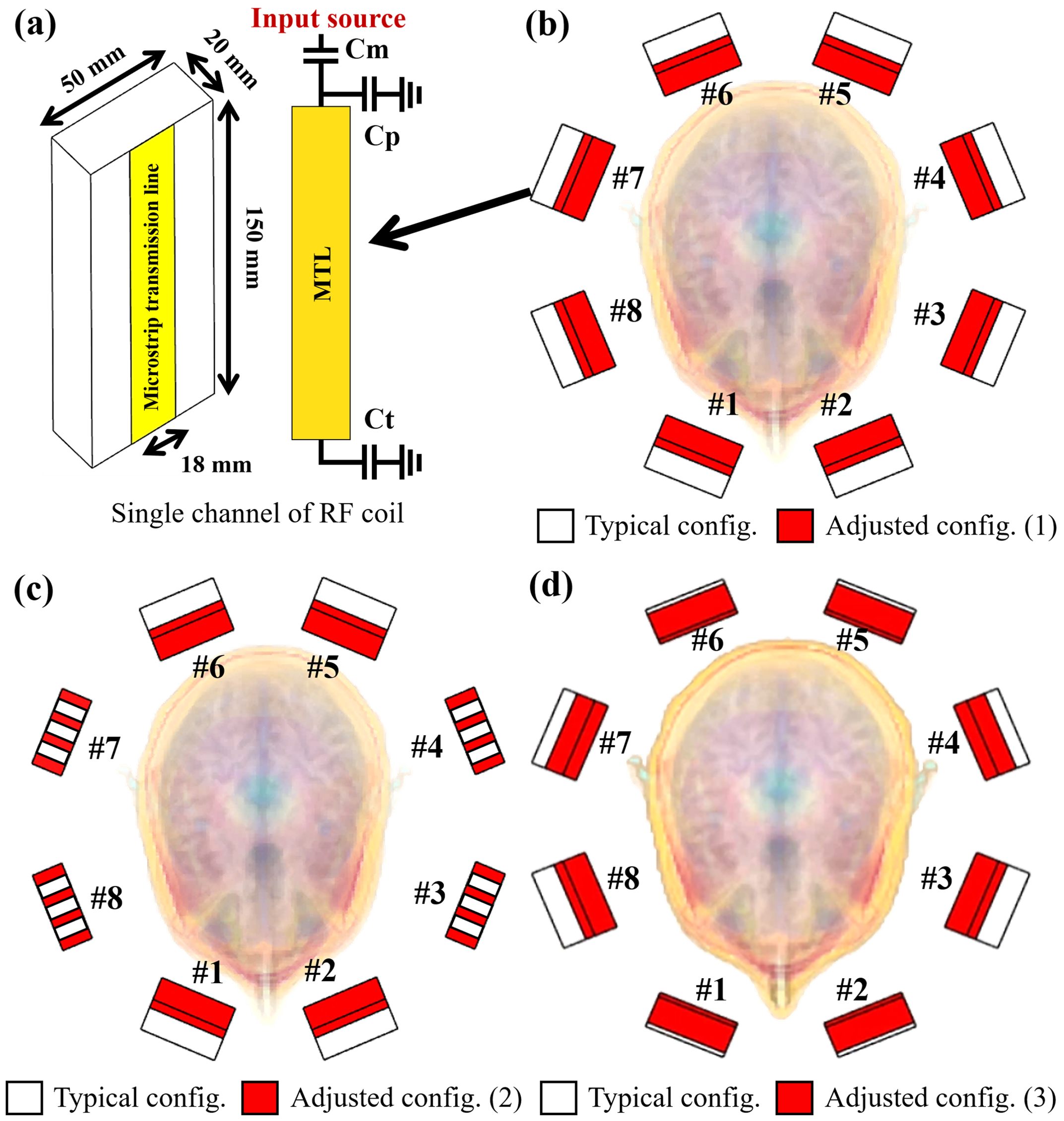
Four different configurations of the multi-channel RF head coil, depicted in Figure 1, were simulated to analyze the effect of the geometrical shape of the coil. Each configuration consists of eight microstrip transmission line (MTL) resonators, and the dimensions and components of the single channel is shown as Figure 1(a). An MTL conductor of with 18 mm and a finite ground plane are employed at a Teflon substrate (εr=2.08, loss tan.=0.004) with width, length, and thickness of 150 mm, 50mm, and 20 mm, respectively. As shown in figure 1(b), typical configuration and adjusted configuration (1) form a circular shape but different diameters. Adjusted configuration (2) and (3) depicted in figure 1(c) and (d) form a oval shape with and without geometrical similarity to the head shape, respectively. The numerical simulations of the configurations were conducted with a realistic human model (DUKE: male, 32 years old) using Sim4Life [5], an commercial simulator based on the finite-difference time-domain (FDTD) method. For the comparison, |B1+| and SAR in 1 gram of the tissue depending on the coil configurations were numerically obtained from three different slices (XY, XZ, and YZ planes) on the head. To neglect the effect of the difference in phase combinations of the channels and superimpose the B1+ magnetic field on the head, the phases of the neighboring channels of the coils are increased by 45 degrees for all the configurations.Results and Discussion
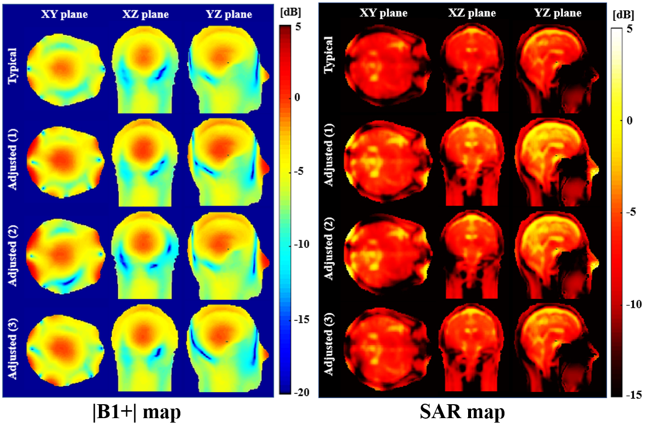
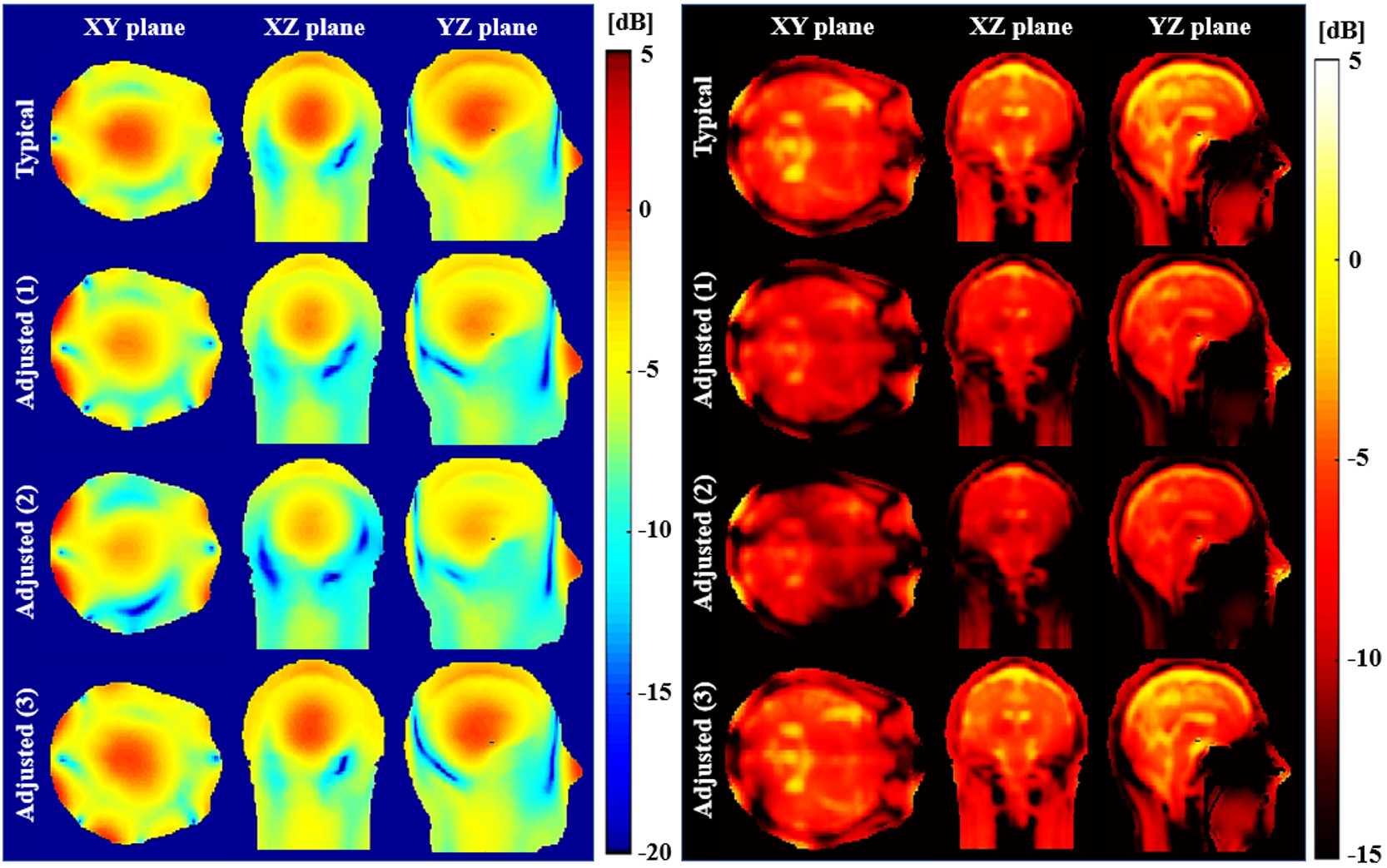
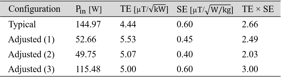
Figure 2 shows the maps of the |B1+| field and SAR produced by the different coil configurations operating at the same power (100W). It is obvious from the results that all the adjusted configurations, in which all or some of the channels were located closer to the head, provide a strong B1+ field on the head compared to the typical coil. Considering that the SAR is rigorously limited for safety consideration, the maps of the |B1+| field and SAR, when the power of all the coil configurations are scaled such that the peak of SAR on the whole head is 8.0 W/kg (FDA limits for local SAR), were also compared as shown in figure 3. For the same peak local SAR, the input power of the typical and adjusted configuration (1), (2), and (3) was 144.97 W, 52.66 W, 49.75 W, and 115.48 W, respectively. The allowable input power of the adjusted configuration (1) and (2) was significantly lower than the others because extremely high local SAR was observed at the near of the head due to the geometrical dissimilarity between the coil and head. In the case of the adjusted configuration (3), almost same intensity of the B+ field was applied throughout the head compared with that provided by the typical coil, even with less input power. To analyze the effect of the configuration on the coil performance with the safety issue, the ratio of the B1+ field to the peak SAR should be evaluated as well as the magnitude of B1+ field acting on the head. Therefore, transmit efficiency (TE), the ratio of the mean of the applied B1+ field and the square root of the total input power, and SAR efficiency, the ratio of the mean of the applied B1+ field and the peak local SAR, were additionally compared as shown in Table I. it is evident from the table that a configuration similar to the head shape is required to optimize the TE and SE performance simultaneously.Acknowledgements
This work was supported by the Basic Science Research Program through the National Research Foundation of Korea (NRF) funded by the Ministry of Science and ICT under Grant 2019R1A2C2004774.
References
[1] G. Adriany, P.-F. Van de Moortele, J. Ritter, et al., “A geometry adjustable 16-channel transmit/receive transmission line array for improved RF efficiency and parallel imaging performance at 7 Tesla,” Magn. Reson. Med., vol.59, pp. 590-597, 2008.
[2] B. Wu, X. Zhang, C. Wang, et al., “Flexible transceiver array for ultrahigh field human MR imaging,” Magn. Reson. Med., vol. 61, pp. 429-438, 2009.
[3] B. Steensma, P.-F. Van de Moortele, A. Erturk, et al., “Introduction of the snake antenna array: Geometry optimization of a sinusoidal dipole antenna for 10.5 T body imaging with lower peak SAR,” Magn. Reson. Med., vol.84, pp. 2885-2896, 2020.
[4] A. S. Tarakameh, G. Adriany, G. J. G. Metzger, et al., “Improving radiofrequency power and specific absorption rate management with bumped transmit elements in ultra-high field MRI,” Magn. Reson. Med., vol.84, pp. 3485-3493, 2020.
[5] Sim4Life by ZMT, www.zurichmedtech.com
Figures