1574
Robust decoupling of a 7 Tesla 8-channel loop array for head and cervical spinal cord imaging1Advanced Imaging Research Center, University of Texas Southwestern Medical Center, Dallas, TX, United States, 2Erik Jonsson School of Engineering and Computer Science at The University of Texas at Dallas, Richardson, TX, United States, 3Philips Healthcare, Gainesville, FL, United States, 4Max Planck Institute for Biological Cybernetics, Tuebingen, Germany
Synopsis
With the guidance of our in-house analytical modeling tool that was developed originally for minimizing both electrical coupling and magnetic coupling , we designed a 7T 8-channel T/R array with robust decoupling performance for both head and cervical spinal cord imaging, and our 7T 8 channel array demonstrated robust decoupling performance for both head and cervical spine cord imaging in both simulations and experiments.
Introduction
With the emerging of advanced MRI applications at ultra-high field, RF array designs with good transmit and receive sensitivity, and good decoupling between the coil elements has become a great priority. However, since the coupling changes with coil loading (1), designing a coil array with robust decoupling performance on different size of subjects is challenging, let alone designing an array for applications in different body parts. In this work, with the guidance of our in-house analytical modeling tool (2), we designed a 7T 8-channel T/R array with robust decoupling performance for both head and cervical spinal cord imaging.Methods
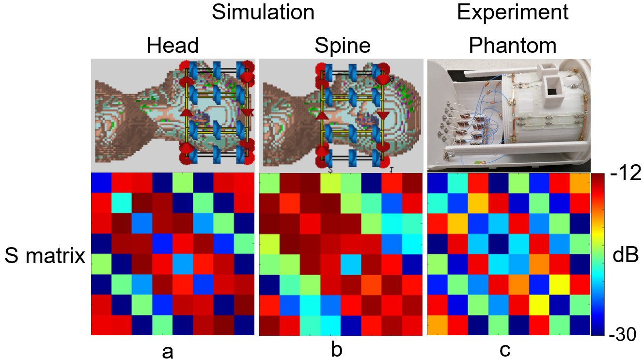
Simulations: Our custom-developed analytical modeling tool (MATLAB) used dyadic Greens functions to calculate electromagnetic fields in a uniform cylindrical phantom (ɛr=80, σ=0.5 S/m). In evaluating the robustness of the coupling, the diameter of the phantom was changed from 100 mm to 220 mm to cover the diameter of head and neck. Two rectangular loop coil elements were placed on a 230mm-diameter cylindrical holder to model the dependence of the coupling on their overlap (2). The width of each coil element was 113.7 mm along the circumference and 160 mm in z direction. The summation of σEi·Ej (i=1, j=2) in the entire phantom was used to evaluate the coupling. Using the same coil size, an 8ch array was modeled in Microwave Studio (Computer Simulation Technology, Darmstadt, Germany) and loaded with a 5mm isotropic Duke (3). A 680 mm-diameter RF shield was included in all simulations and no local RF shield was used (4). The array was first centered at the head and was matched to 50 ohm at 298 MHz in co-simulation. Then the array was shifted towards the cervical spinal cord with the edge of the coil being 1cm away from the shoulder without re-tuned or re-matched to the second position. B1+ maps of the circular-polarization (CP) mode were derived from the simulations, and the input transmit power in both cases was identical.Coil Design and Experiments: The coil frame was 3D printed using polycarbonate (Fortus MC450, Stratasys). The inner diameter of the coil was 220 mm. Eight coil elements were integrated in one row on the coil frame. The single coil element was 160mm in z direction and 113.7 mm in the width. The width was varied lately to adjust the 21.4mm overlap for best decoupling on workbench. Copper width of the coil element was 6mm. An in-house built 1:8 power splitter that evenly split power with 45° phase offset step was connected to the 8 coil elements to drive the array in CP mode. Eight in-house built T/R switches were used to switch the array between transmit and receive modes. The array was connected to a human whole-body 7T MRI system (Philips Healthcare) via the standard interface boxes provided by the manufacturer. Human subject studies were performed following a protocol approved by our institutional review board, and informed consent was obtained from each subject. The transmit power was calibrated for the head imaging and was kept the same for the cervical spinal code imaging. The actual flip angle imaging (AFI) (5) dual-TR method was used to acquire the experimental flip angle map. In vivo T1 weighted images of the head were acquired with a 3D MP2RAGE sequence (6). In vivo T2* weighted images of the cervical spinal cord were acquired with a multi-echo 3D Fast Field Echo (FFE) sequence (7). All the echoes were summed up for the final FFE image.
Results and Discussion
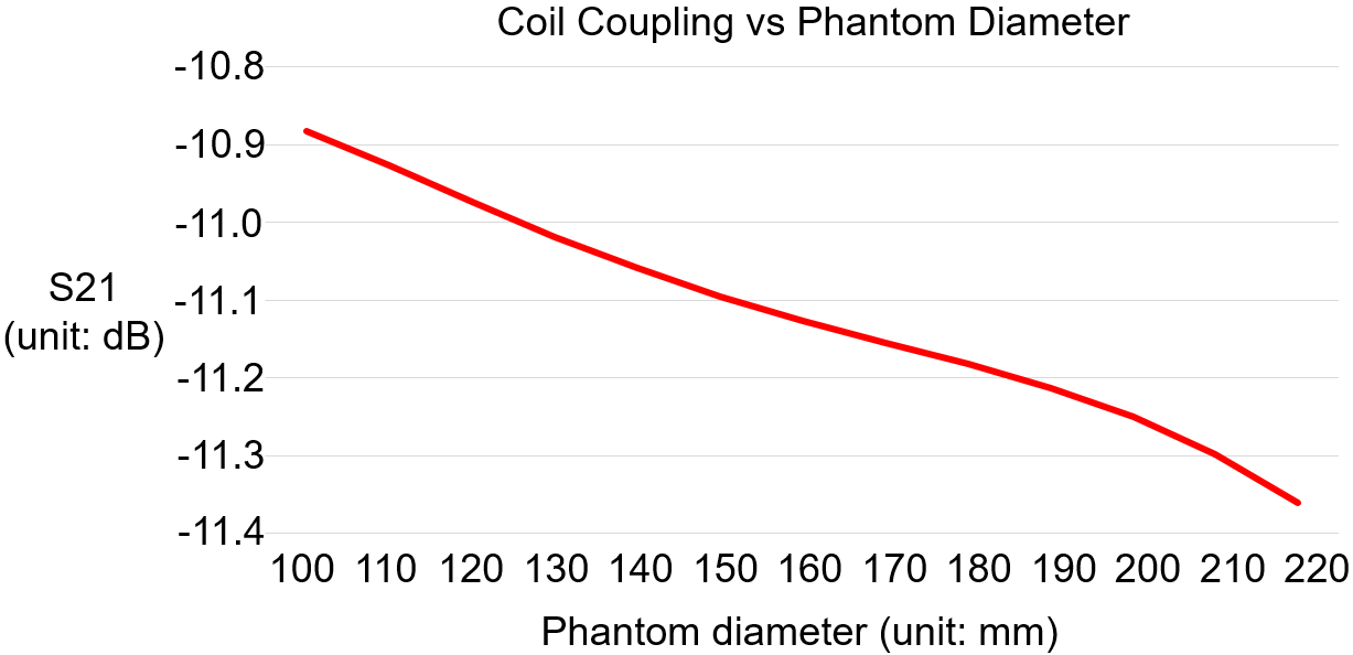
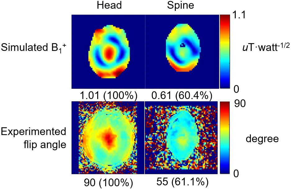
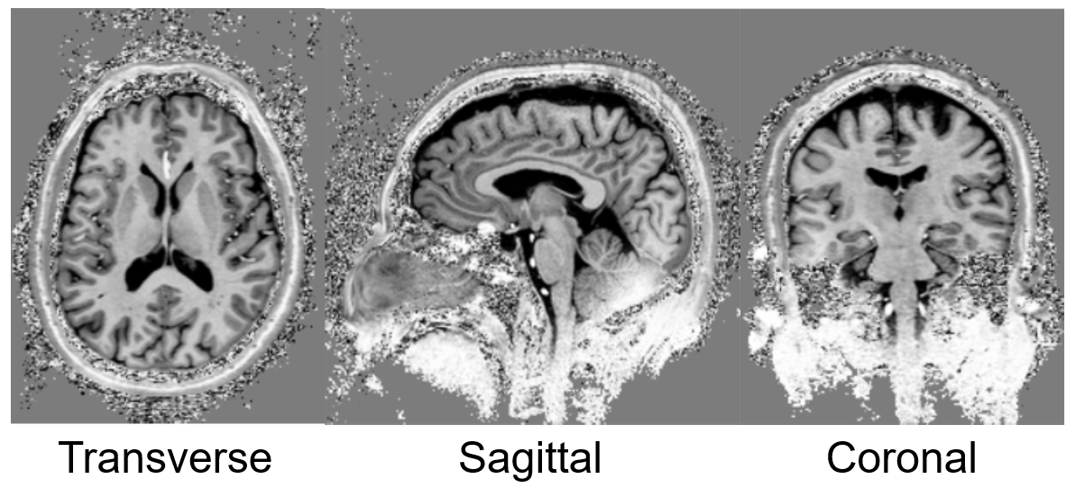
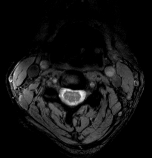
Simulations: S21 between each adjacent pair of coil elements changed by 0.48dB from -11.36 to -10.88 dB when the phantom diameter changed from 220mm to 110mm in our analytical modeling tool (Figure 1). In CST, the maximal S21 of the array changed from -14.0dB in the head to -12.2dB when shifted to cervical spinal cord. This small change in coupling is indicative of the insensitivity of the coil array to different load. The S11 was lower than -20dB when loaded with the head and was lower than -13dB when shifted to the cervical spine, as shown in Figure 2a and 2b. With the same input power, the transmit field was 60.4% in the cervical spinal cord of that in the head. Experiments: The ratio of unloaded-to-loaded quality factor of a single coil element was 9.52, and S21 was lower than -13.8dB (Figure 2c) when loaded with a 170 mm-diameter cylindrical phantom (ɛr=80, σ=0.5 S/m). With the same transmit power to achieve 90° flip angle in the head, we achieved 55° degree (61.1%) in the cervical spine, as shown in Figure 3, bottom row. This was consistent with the simulation results. Figure 4 shows MP2RAGE images of the human head in three radiographic planes. Part of the cerebellar lobe was not covered and to do so, another row of coil elements or cross-loops on top are needed to extend the z coverage of the array(8). Figure 5 shows an in-vivo in-plane high resolution axial T2-weighted image of the cervical spinal cord with good grey and white matter contrast.Conclusion
Our 7T 8 channel array demonstrated robust decoupling performance for both head and cervical spine cord imaging in both simulations and experiments.Acknowledgements
The authors very much appreciate the funding that makes this work possible: Cancer Prevention and Research Institute of Texas, Grant Number: RR180056References
1. Roemer PB, Edelstein WA, Hayes CE, Souza SP, Mueller OM. The NMR phased array. Magn Reson Med 1990;16(2):192-225.
2. Avdievich NI, Pfrommer A, Giapitzakis IA, Henning A. Analytical modeling provides new insight into complex mutual coupling between surface loops at ultrahigh fields. NMR Biomed 2017;30(10).
3. Christ A, Kainz W, Hahn EG, Honegger K, Zefferer M, Neufeld E, Rascher W, Janka R, Bautz W, Chen J, Kiefer B, Schmitt P, Hollenbach HP, Shen J, Oberle M, Szczerba D, Kam A, Guag JW, Kuster N. The Virtual Family--development of surface-based anatomical models of two adults and two children for dosimetric simulations. Phys Med Biol 2010;55(2):N23-38.
4. Zhang B, Adriany G, Delabarre L, Radder J, Lagore R, Rutt B, YANG XQ, Ugurbil K, Lattanzi R. Effect of radiofrequency shield diameter on signal-to-noise ratio at ultra-high field MRI. Magn Reson Med. 5. Yarnykh VL. Actual flip-angle imaging in the pulsed steady state: a method for rapid three-dimensional mapping of the transmitted radiofrequency field. Magn Reson Med 2007;57(1):192-200.
6. Marques JP, Kober T, Krueger G, van der Zwaag W, Van de Moortele PF, Gruetter R. MP2RAGE, a self bias-field corrected sequence for improved segmentation and T1-mapping at high field. Neuroimage 2010;49(2):1271-1281.
7. van der Meulen P, Groen JP, Tinus AM, Bruntink G. Fast Field Echo imaging: an overview and contrast calculations. Magn Reson Imaging 1988;6(4):355-368.
8. Avdievich NI, Giapitzakis IA, Bause J, Shajan G, Scheffler K, Henning A. Double-row 18-loop transceive-32-loop receive tight-fit array provides for whole-brain coverage, high transmit performance, and SNR improvement near the brain center at 9.4T. Magn Reson Med 2019;81(5):3392-3405.
Figures