1571
Design and evaluation of a 2-Tx 24-Rx coil for 5T knee MR imaging1United Imaging Healthcare, Shanghai, China, 2Lauterbur Imaging Research Center, Shenzhen Institutes of Advanced Technology, Chinese Academy of Science, Shanghai, China
Synopsis
Musculoskeletal imaging is one widely used MR application with advantages in exquisite details of anatomic structure, rich contrast options for various soft tissues and high diagnostic accuracy [1]. The SNR gain of high field MRI can further help extending such applications as magnetic resonance knee imaging. A 2-channel birdcage transmit and 24-channel loop array receive coil is designed and evaluated on the novel whole body 5T MRI scanner (United Imaging Healthcare, Shanghai, China, abbreviated as UIH below). The imaging performance is compared with a 3T scanner and the results are discussed.
Synopsis
Musculoskeletal imaging is one widely used MR application with advantages in exquisite details of anatomic structure, rich contrast options for various soft tissues and high diagnostic accuracy [1]. The SNR gain of high field MRI can further help extending such applications as magnetic resonance knee imaging. A 2-channel birdcage transmit and 24-channel loop array receive coil is designed and evaluated on the novel whole body 5T MRI scanner (United Imaging Healthcare, Shanghai, China, abbreviated as UIH below). The imaging performance is compared with a 3T scanner and the results are discussed.Introduction
In typical musculoskeletal applications, high scan resolution is preferred to illustrate details of muscles, ligaments, and tendons where hardware SNR is essential for image quality. Another challenge is the small scanning FOV which could lead to aliasing artefacts that require additional phase encoding. A local transmit and receive coil at 5T field strength will meet the growing SNR demand and provide localized excitation region that can reduce time penalty of extra phase encoding.Methods
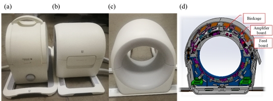
The receive array is designed with a toroidal diameter of 170mm and axial coverage of 180mm. The 24 coil elements are arranged in a 3 row by 8 elements array structure with element size of approximately 8cm by 8cm. The transmit coil is designed as a 16-rung high-pass birdcage with 2 independent driving ports. An RF shield is introduced to reduce radiation losses and interactions between the volume whole body transmit coil, as well as avoid transmit field leak out to the neighbor extremity. The overall coil is designed as a stacked structure of the receive and transmit part. Compact layout feeding and amplifier boards are mounted in remnant spaces between legs and shields of the birdcage transmit coil.A standard gradient echo (GRE) is used for both B1+ field distribution and receive SNR measurements. The TE/TR scan parameters are set as 8ms/1000ms to minimize different relaxation effect between 3T and 5T system. The B1+ was tested by GRE double angle scans with flip angles 30 and 60. The SNR scan uses a signal scan with flip angle 30 and a noise scan with flip angle 0. The SNR calculation is based on the standard procedure proposed by Kellman [2]. And the flip angle map obtained with double angle scan is used to eliminate the effect of transmit field inhomogeneity in SNR result. The test phantom is cylindrical shaped with a 110mm diameter. The filler is 1.24g NiSO4*6H2O and 5g NaCl per 1000 ml water.
In human scan, a standard Fast Spin Echo (FSE) sequence is used in the human knee scan. It is set as a proton density map with 2800ms TR and 88ms effective TE with fat saturation. The scan resolution was tuned down to voxel size of 0.1mm3 with RO/PE size of 0.2mm and thickness of 2.5mm.
Results
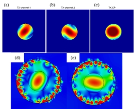
With the stacked structure of the receive and transmit layers, the coil contour is 2cm smaller than the 3T coil, as shown in the figure 1. The T/R coil is 4cm longer than the 3T coil to obtain larger axial coverage since aliasing ghosts are eliminated with the local transmit coil.The measured and simulated transmit B1+ field of the 2-port birdcage coil is shown in figure 2. The actual field distribution of single channel excitation is consistent to simulation result with balanced amplitude and rotational symmetry. The default 2 channel circularly polarized transmit mode has a slightly elliptical distribution so B1 shimming of exact channel amplitude and phase is needed to produce a perfectly symmetric result.
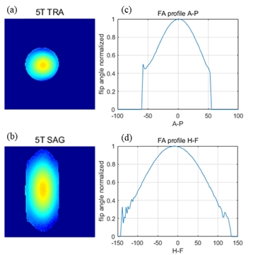
The normalized transmit B1+ distribution of the 5T local birdcage is shown in figure 3. In the transverse plane, a 55% roll-off on the edge is observed with regard to the center region of phantom. In the sagittal plane, it is shown that the B1+ field is confined in a 180mm axial region for the 5T local transmit case, defined by 50% roll-off with respect to coil center.
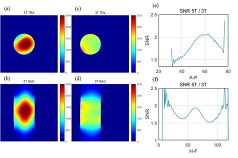
The SNR of the 5T coil is substantially higher than the 3T coil as shown in figure 4. Effect of B1+ inhomogeneity on signal intensity distribution is compensated with the flip angle map result. In the transverse plane, the 5T SNR in central region of phantom is roughly 1.5~2 times to the 3T case. In the sagittal plane, distinct sensitivity distribution can be observed due to different receive array structure, in which the 5T coil has 3 toroidal section but the 3T coil has only 2 sections.
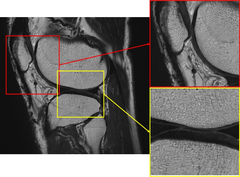
The SNR gain of the 5T knee coil was utilized to produce high resolution clinical imaging shown in figure 5. In the proton density FSE scan, the resolution down to 0.1mm3 can help to reveal fine structure of articular cartilage, meniscus, and ligaments.
Discussions and Conclusions
The performance of the 5T 2-TX 24-RX knee coil is fully evaluated in phantom tests for both transmit and receive performance. Substantial SNR gain is achieved in comparison with a 3T coil and high-quality clinical images are acquired. The improved imaging resolution can be utilized to reveal small lesions in knee joint region.Acknowledgements
This work is supported by National Key R&D Program of China NO.2017YFC0108800References
[1] D. Solomon, Trends in Knee Magnetic Resonance Imaging, Medical Care, vol.41 no.5,pp:687-92
[2] P. Kellman, Image reconstruction in SNR units: a general method for SNR measurement, Magneticresonance in medicine, vol.54, no.6, pp. 1439-1447
Figures