1426
A 30-element transmit array for 7 Tesla brain imaging with array compressed parallel transmission1Vanderbilt University Institute of Imaging Science, Nashville, TN, United States, 2Biomedical Engineering, Vanderbilt University, Nashville, TN, United States, 3Radiology, Vanderbilt University, Nashville, TN, United States, 4Electrical and Computer Engineering, Vanderbilt University, Nashville, TN, United States
Synopsis
A dense array is desirable for ultra-high field in parallel transmission to better mitigate B1+ field inhomogeneities and control specific absorption rate. Most ultra-high field scanners are limited by the existing number of transmit channels. This limitation can be overcome using array-compressed parallel transmission (acpTx) which enables a small number of channels to drive a large number of coils. This work describes the construction of a 30-loop head transmit array using a mixed overlapped and self-decoupled design with a widely-used commercial 32-channel receive insert for human imaging applications.
Purpose
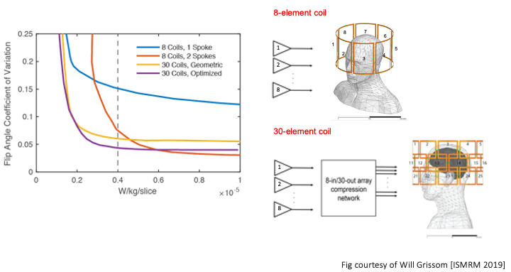
A many-coil array is desirable for ultra-high field in parallel transmission to better mitigate B1+ field inhomogeneities and control specific absorption rate (SAR). Most ultra-high field scanners are limited by the number of transmit channels outfitted in the scanner’s original siting. This limitation can be overcome using array-compressed parallel transmission (acpTx)1 which enables a small number of channels to optimally drive a large number of coils. The simulations in Fig.1 show that a population-optimized fixed 8-input acpTx network driving 30 coils achieves a large improvement in the tradeoff between flip angle uniformity and SAR compared to a conventional 8-element coil2. This work describes the construction of the 30-loop head transmit array used in these simulations, to verify this result experimentally. This will be the first time an array-compressed coil and network have been jointly designed for a human imaging application. We previously described an initial mixed overlapped and self-decoupled design for this coil that achieves better decoupling than overlap alone3. Here we detail further progress on this coil’s construction and integration with a widely-used commercial 32-channel receive insert and provide CAD files of the former and boards available for use at https://github.com/csappo/pTx.Methods
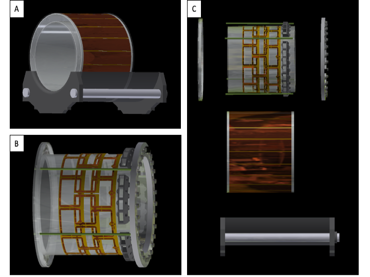
Mechanical designThe coil is designed so that a Nova 32-coil receive array fits inside it (Wilmington, MA, USA), for a Philips Achieva 7T MRI scanner (Philips, Best, Netherlands). The mechanical design encompasses the former with strain relief and the sliding mechanism to mimic the 8-channel Nova transmit coil mechanism so the receive array can be easily swapped in and out as shown in Fig.2A. The former is a cast acrylic tube (OD=11 3/8”,wall thickness=1/8”) with a slotted shield (OD=14”,wall thickness=1/8”)4 all with a length of 13”. The coil’s length was minimized to accommodate the future acpTx network. Shown in Fig.2B, the coil tube and the shield tube are held together in tension created by endrings that slide into the scanner bed and wrapped in cellulose film to protect the shield. The end rings are machined from ½” acrylic and the rods are ½” fiberglass rods. The middle row of coils is split in half and designed to be bolted on, and spacers are in place to guarantee that the spacing from the other rows is consistent. Each coil has a BNC connector on the back endring to easily swap out cables when needed. This will be important for incorporating the acpTx network at the back of the coil. Fig.2C shows that the former can be easily taken apart, modified and reassembled if the coil needs to be serviced or any of the components upgraded.
Electrical design
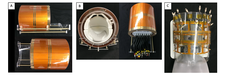
The loops are constructed in sets of five from flexible PCB material (thickness=0.1mm) from PCB Way (Wan Chai, HK). The rectangular loops are 7.5cm x 8.7cm with an unequal distribution of capacitors and inductors to implement self-decoupling5,6. Additionally, the PCB has a lattice balun with values of ~23nH and ~11pF for a balanced and unbalanced impedance of 50-ohms at 298MHz. Fig.3A shows the constructed coil in the housing and the sliding patient mechanism. Fig.3B shows how the receive array fits inside the former, which is a design requirement for this coil. Fig.3C shows the populated coil as used for the bench results. All measurements were taken using length matched cables. Foam was used to prop the cables away from the coil until permanent cables are installed.
Results
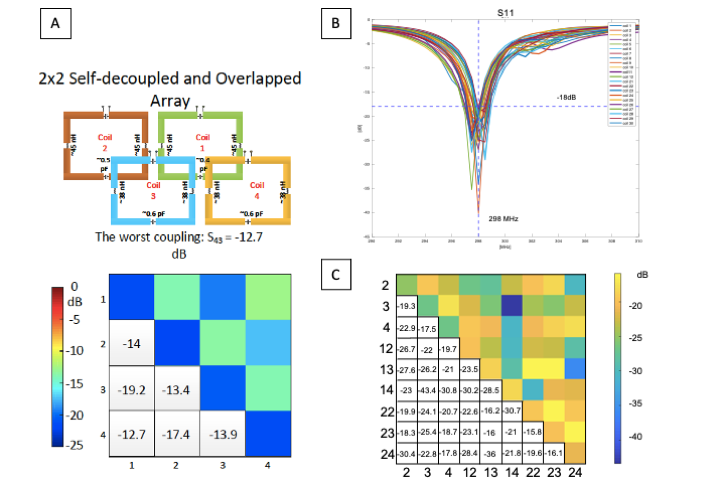
Simulation results are shown for a 2x2 coil array in Fig.4A which was used to guide the decoupling strategy for the entire coil. The simulations show that using self-decoupling for nearest-neighbors in the same row and overlapping for nearest-neighbors in different rows maintains decoupling that is better than -12.7dB. Next-nearest-neighbor coupling is not an issue using this strategy because the coils are physically distant and no additional decoupling is needed. The scattering matrix results for tuning and matching at 298MHz are shown in Fig.4B All 30 traces are shown on the same plot for comparison with the worst match –18.3022dB and an average -22.4658dB. Fig.4C, shows a subset of decoupling results. This includes a 3x3 coil s-matrix that is representative of the entire array. The decoupling results are plotted like this for ease of understanding. The worst decoupling was between coil 22 and coil 23 at -15.8469dB.Discussion and Conclusion
We have described a 30-element transmit array coil for in vivo array compressed parallel transmission that combines self-decoupling and overlapping, and accommodates a widely used 32-channel receive array. The elements could also be inductively or capacitively decoupled, but these methods increase the number of components and thereby increase construction complexity compared to overlapping and self-decoupling. Combining overlapping and self-decoupling enables coils to be fabricated row-by-row, making the construction easier since horizontal coils don’t need their overlap adjusted. Next, we will add cabling and sleeve baluns7 to the array. When constructing a dense array, special attention needs to be given to the cable placement to ensure they are not interacting with the coils or other cables. We have presented results here based on bench measurements from phantom loading, matching and coupling results are likely to vary with different head sizes. If unacceptable, additional decoupling strategies will be considered.Acknowledgements
The authors thank Gabriela Gallego for her input on the strain relief design. Additionally, the authors thank Markus May for thoughtful discussions and advice on shielding requirements.
This work was supported by NIH grants R01 EB 016695 and U01 EB 025162.
References
[1] Yan, X., Cao, Z., & Grissom, W. A. (2016). Experimental implementation of array‐compressed parallel transmission at 7 tesla. Magnetic resonance in medicine, 75(6), 2545-2552.
[2] Grissom, W.A., Yan,X., & Cao, Z. Universal Coils: Multisubject Optimization of 8-Channel Many-Element Parallel Transmit Arrays. In 27th Annual Meeting of ISMRM, Montreal, Quebec.
[3] Sappo, CR., Grissom, W.A., Yan, X. On the Design of a 30-Element 7T Head Transmit Array Combining Overlapping & Self-Decoupling. In 2019 ISMRM Workshop on Ultrahigh Field Magnetic Resonance in Dubrovnik, Croatia.
[4] Stockmann, J. P., Witzel, T., Arango, N., Mareyam, A., Sappo, C., Zhou, J., Park, J., Jenkins, L., Keil, B., Polimeni, J. R., White, J., Wald, L. L. An integrated 32ch RF-shim array coil for improved B0 shimming of the brain at 7 Tesla. In 25th Annual Meeting of ISMRM, Honolulu, HI, USA.
[5] Yan, X., Gore, J. C., & Grissom, W. A. Multi-row and Loopole-type Self-decoupled RF Coils. In 26th Annual Meeting of ISMRM, Paris, France.
[6] Yan, X., Gore, J. C., & Grissom, W. A. (2018). Self-decoupled radiofrequency coils for magnetic resonance imaging. Nature communications, 9(1), 3481.
[7] Seeber DA, Jevtic I, Menon A. Floating shield current suppression trap. Concepts In Magnetic Resonance 2004; 21B: 26–31.
Figures