1424
Optimization of a massive-element self-decoupled transmit array for 7T head imaging1Vanderbilt University Institute of Imaging Science, Nashville, TN, United States, 2Department of Radiology and Radiological Sciences, Vanderbilt University Medical Center, Nashville, TN, United States
Synopsis
At high fields, B1 inhomogeneity is one of the major challenges that limit imaging performance. Parallel transmission with an array of coils is a recognized solution to B1 inhomogeneity. The self-decoupled coil is attractive in Tx array design since it exhibits intrinsic inter-element isolation that may ease the coil fabrication, and allows the dipole mode as well as loop mode. In this work, we evaluated a series of self-decoupled coils in terms of these parameters and aimed to provide guidance for the practical building of a high-performance self-decoupled Tx array.
Purpose:
B1 inhomogeneity is one of the major challenges at high fields. Parallel transmission with an array is a recognized solution to this problem. Parallel transmit arrays, which allow the independent control of individual elements with amplitude and phase modulations, can ameliorate and even correct B1 inhomogeneities, and are widely employed in ultra-high field MRI scanners [1-7]. Various Tx array designs have proposed, using loop, stripline, dipole, or mixed structures. In dense Tx arrays that have strong inter-element crosstalk, various decoupling technologies have been used, such as overlapping, shielding, passive resonator, and the recently-proposed self-decoupling [8-11]. The self-decoupled coil is attractive in Tx array design since it exhibits intrinsic inter-element isolation that may ease the coil fabrication, and allows the dipole mode as well as loop mode [12, 13]. Self-decoupled arrays have been investigated in previous works by evaluating the RF shimming and/or parallel transmission capability in terms of transmit field uniformity and SAR. For Tx arrays, however, the power efficiency (or transmit efficiency, B1+/√W), decoupling/matching robustness, detune ability also play important roles in real coil fabrication. In this work, we evaluated a series of self-decoupled coils in terms of these parameters and aimed to provide guidance for the practical building of a massive-element self-decoupled Tx array.Methods:
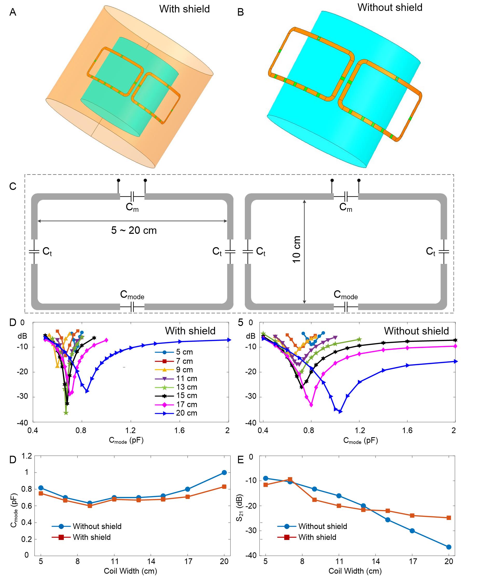
We first investigated two side-by-side self-decoupled loops with different coil sizes in EM simulation (Ansys HFSS and Designer, Canonsburg, PA, USA). Figure 1A and 1B show simulation model with and without shield. Coils were mounted on a 29-cm-diameter cylindrical tube, with a 19-cm-daimeter phantom placed 5cm below. The electromagnetic properties of the phantom were set to the those of average brain tissues. The coil length (along z-direction) is set with a fixed value of 10 cm, while the coil width (along the circumference direction) varied across 5cm to 20 cm. Cmode of each case was determined was following the method in Ref [11]. These simulations were performed in two scenarios, without an RF shield and with a 35-cm-diameter RF shield. After the two-loop simulations, we also investigated up to 24 self-decouple dipoles[13] + 24 self-decoupled loops with the optimal coil width of 15 cm. Details about the coil width optimization will be described later in the Results Section. This width is optimized by considering the decoupling ability, value of Cmode, decoupling robustness, power efficiency, and the number of coils.Results and Discussions:
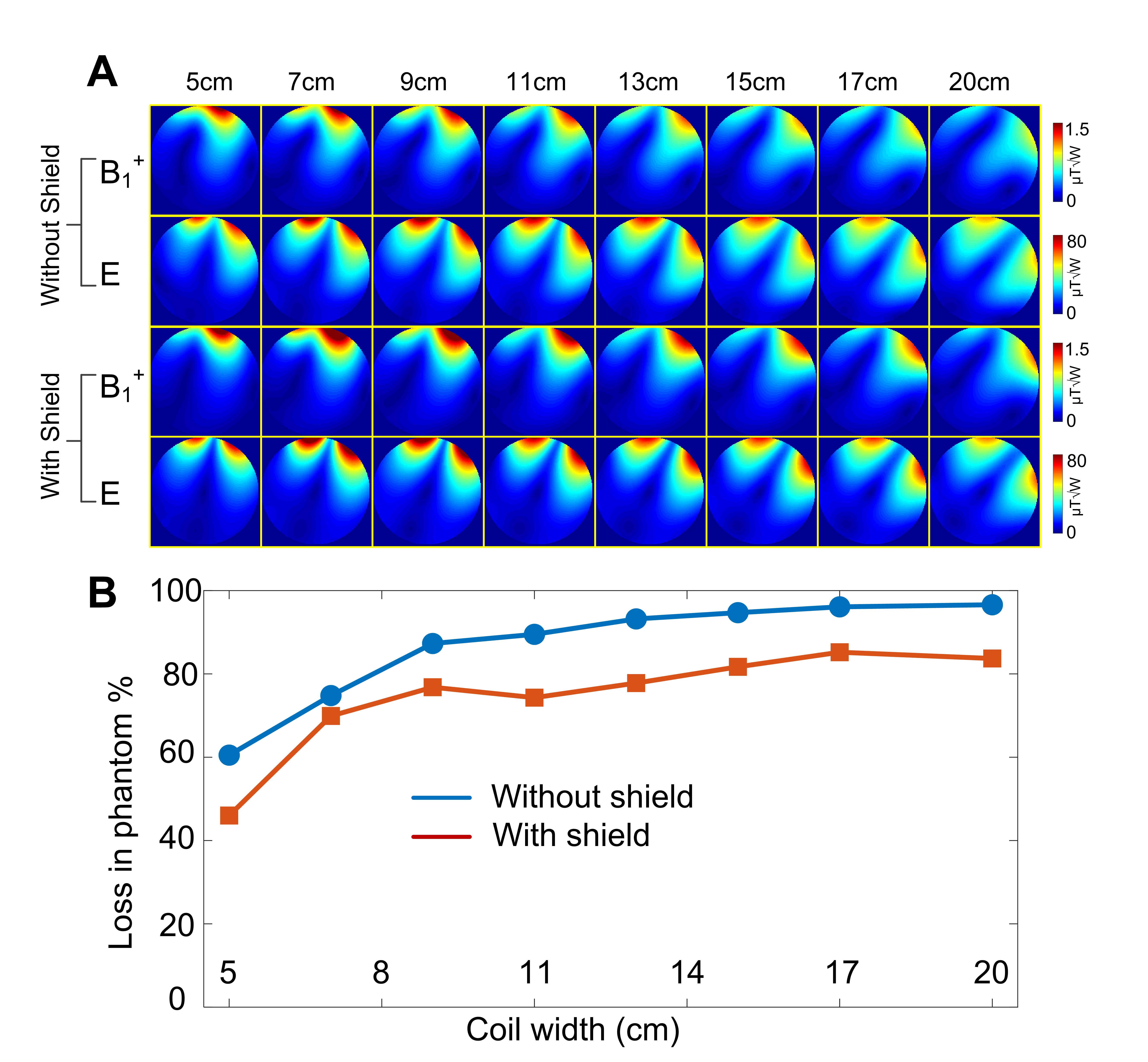
Figure 1C shows the circuit diagram of two side-by-side self-decoupled coils. Cmode is for decoupling performance, Ct (could also be inductor) is for tuning, and Cm is for matching. Figures 1D and 1E plots the coil decoupling (S21) versus different Cmode, with coil width from 5cm to 20 cm. It is found that the best isolation could only be ~10 dB when coil width <=7cm. Although the 9-cm-wide coil can achieve -16 dB with the RF shielding, its optimal Cmode falls into a quite small range, which will decrease the decoupling robustness and thus coil robustness. To achieve decoupling ability better than -20 dB, the coil width is suggested to be at least 13 cm (Figure 1G). Note that the decoupling performance is also affected by the loading. The phantom-to-coil distance set here represents the average coil-to-head distance in local Tx-only coils.Figure 2A show B1+ and electric (E-) field of a single self-decoupled with different coil widths. It is noted that smaller coil has stronger B1+ near the surface area, while the large coils have better penetration but lower local B1+. It is also not suggested to use the coil width up to 20 cm since it reduce the number of coils and the B1+ and E penetration are too strong that may cause unwanted coupling with opposite elements. Figure 2B analyzed the power loss in the phantom. In the ideal case, 100% power will be dissipated in the phantom and contribute to the B1+ field. However, due to the coil loss, radiation loss, and RF shielding loss, small coils have considerable power dissipated outside the phantom and wasted. To achieve >80% power loss in the phantom, the coil size is suggested to be >=15cm.
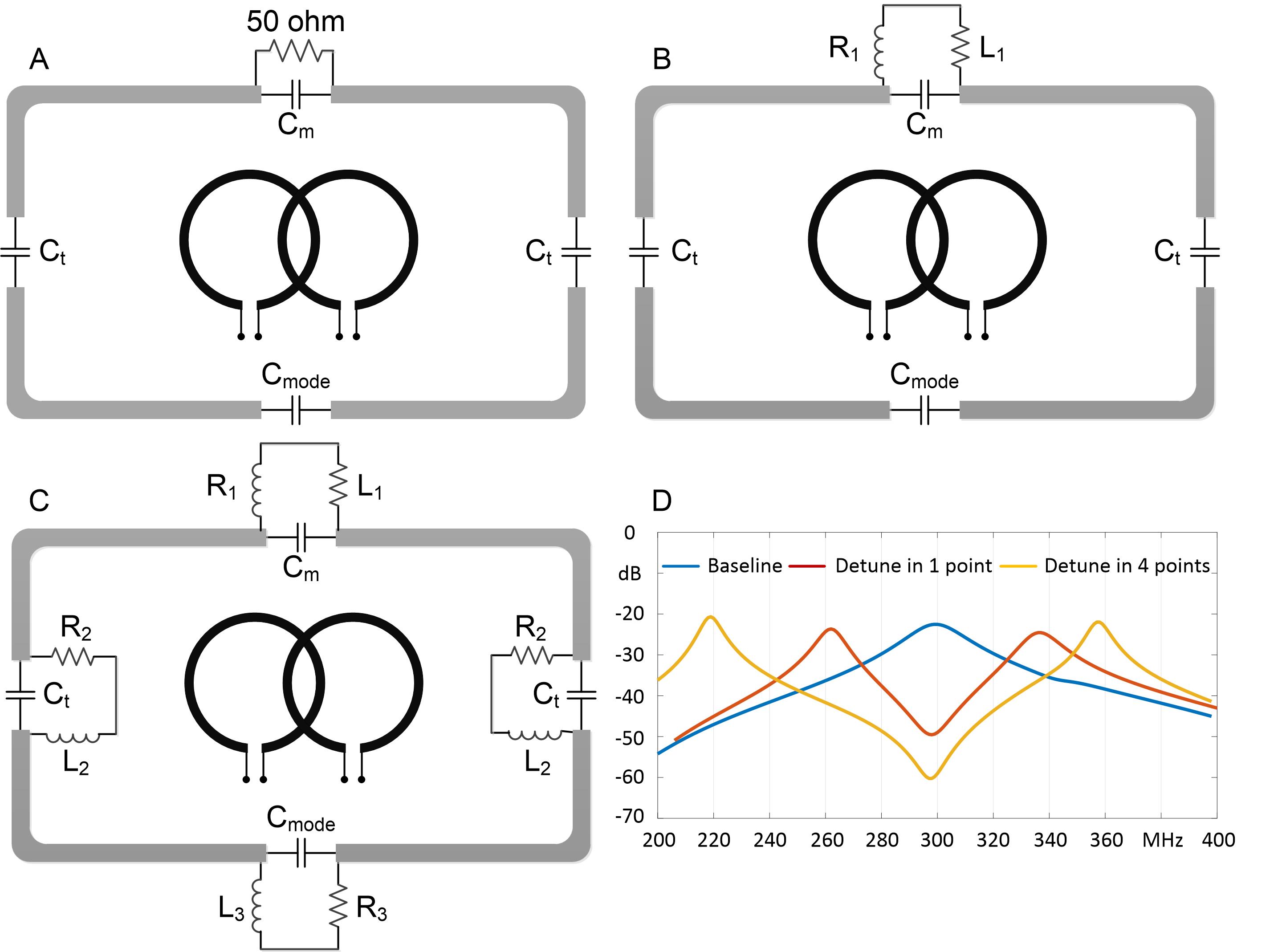
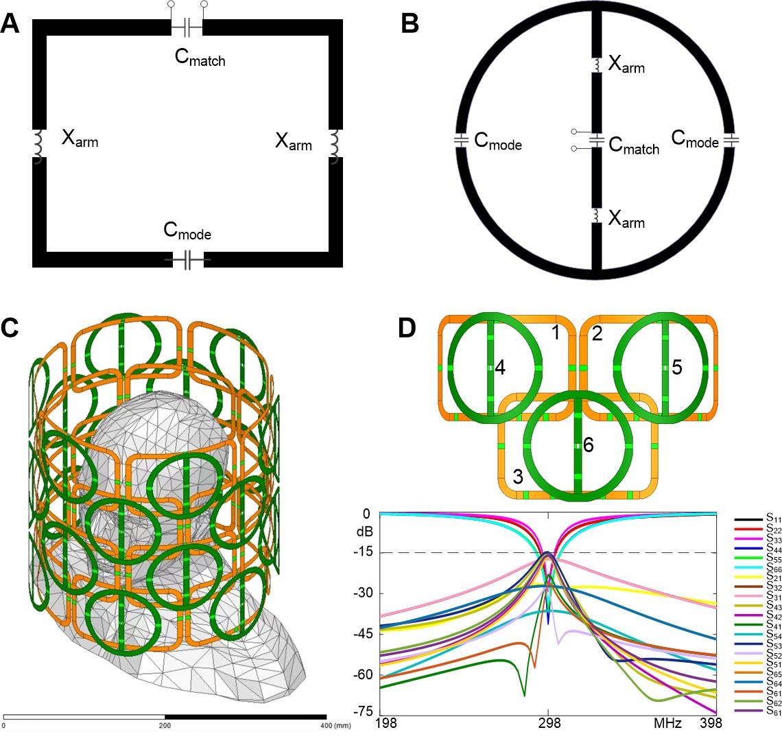
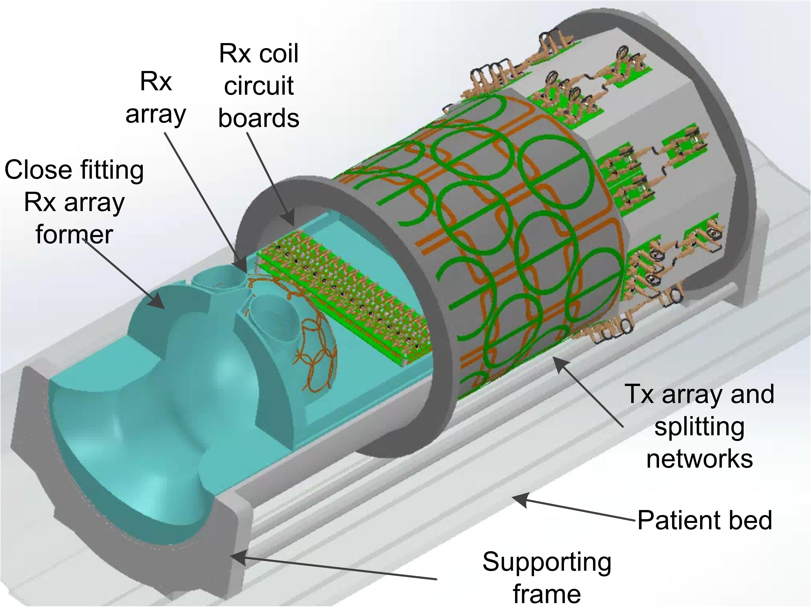
Based on the results in Figures 1 and 2, the optimal coil width will be ~15cm. Figure 3 shows the detune performance of such a 15-cm-wide coil. By employing one detune circuit across the Cmode, ~26dB detune can be obtained. We also noted that detune ability to increase by 11dB by increasing number of detune circuits to 4. Figure 4 shows the simulation results of a Tx-only array with 24 self-decouple loops (using the optimal coil width of 15cm) and 24 self-decouple dipoles [13]. It is noted that the decoupling among all elements could be better than -15dB on a human head model. Figure 5 shows the SolidWorks drawing of the 48-element Tx-only coil with an close-fitting Rx-only coil inserted.
Conclusion:
For the first time, we investigated how the coil size affect self-decoupled coils' performance in terms of decoupling ability, robustness, power efficiency, and etc. A 48-element self-decoupled head Tx array using the optimized size was simulated with the human model, and it is found this coil exhibits high inter-element isolation (<-15 dB) as well as the high transmit efficiency.Acknowledgements
No acknowledgement found.References
1. Zhu Y. Parallel excitation with an array of transmit coils. Magn Reson Med. 2004;51(4):775-84. Epub 2004/04/06. doi: 10.1002/mrm.20011. PubMed PMID: 15065251.
2. Adriany G, Van de Moortele PF, Ritter J, Moeller S, Auerbach EJ, Akgun C, et al. A geometrically adjustable 16-channel transmit/receive transmission line array for improved RF efficiency and parallel imaging performance at 7 Tesla. Magn Reson Med. 2008;59(3):590-7. Epub 2008/01/26. doi: 10.1002/mrm.21488. PubMed PMID: 18219635.
3. Mao W, Smith MB, Collins CM. Exploring the limits of RF shimming for high-field MRI of the human head. Magn Reson Med. 2006;56(4):918-22. Epub 2006/09/08. doi: 10.1002/mrm.21013. PubMed PMID: 16958070; PubMed Central PMCID: PMCPMC4040521.
4.Orzada S, Bitz A, Gratz M, Johst S, Shooshtary S, Voelker M, et al., editors. A 32-channel transmit system add-on for 7 Tesla body imaging. Proc Intl Soc Mag Reson Med; 2017.
5. Raaijmakers AJ, Ipek O, Klomp DW, Possanzini C, Harvey PR, Lagendijk JJ, van Den Berg CA. Design of a radiative surface coil array element at 7 T: the single‐side adapted dipole antenna. Magnetic resonance in medicine. 2011 Nov;66(5):1488-97.
6. Alagappan V, Nistler J, Adalsteinsson E, Setsompop K, Fontius U, Zelinski A, et al. Degenerate mode band-pass birdcage coil for accelerated parallel excitation. Magn Reson Med. 2007;57(6):1148-58. Epub 2007/05/31. doi: 10.1002/mrm.21247. PubMed PMID: 17534905.
7. Metzger GJ, Snyder C, Akgun C, Vaughan T, Ugurbil K, Van de Moortele PF. Local B1+ shimming for prostate imaging with transceiver arrays at 7T based on subject-dependent transmit phase measurements. Magn Reson Med. 2008;59(2):396-409. Epub 2008/01/30. doi: 10.1002/mrm.21476. PubMed PMID: 18228604; PubMed Central PMCID: PMCPMC4406352.
8. Avdievich NI. Transceiver-Phased Arrays for Human Brain Studies at 7 T. Appl Magn Reson. 2011;41(2-4):483-506. Epub 2011/12/01. doi: 10.1007/s00723-011-0280-y. PubMed PMID: 23516332; PubMed Central PMCID: PMCPMC3600590.
9. Gilbert KM, Belliveau JG, Curtis AT, Gati JS, Klassen LM, Menon RS. A conformal transceive array for 7 T neuroimaging. Magn Reson Med. 2012;67(5):1487-96. Epub 2011/12/23. doi: 10.1002/mrm.23124. PubMed PMID: 22190335.
10. Li Y, Xie Z, Pang Y, Vigneron D, Zhang X. ICE decoupling technique for RF coil array designs. Medical physics. 2011 Jul;38(7):4086-93.
11. Yan X, Gore JC, Grissom WA. Self-decoupled radiofrequency coils for magnetic resonance imaging. Nature communications. 2018 Aug 28;9(1):1-2.
12. Yan X, Gore JC, Grissom WA. Multi-row and Loopole-type Self-decoupled RF Coils, ISMRM 2018, p4271.
13. Lu M, Gore JC, Yan X. Self-decoupled Folded Dipole Antenna, ISMRM 2020, p4054.
Figures