1423
Combining Loops and Dipoles to Increase the Signal-to-Noise Ratio in Human Brain MRI at 7T: How to Shorten a Dipole Antenna?1Laboratory of Functional and Metabolic Imaging (LIFMET), Ecole Polytechnique Federale de Lausanne (EPFL), Lausanne, Switzerland, 2CIBM Center for Biomedical Imaging, Lausanne, Switzerland, 3Animal Imaging and Technology, Ecole Polytechnique Federale de Lausanne (EPFL), Lausanne, Switzerland
Synopsis
Dipole antennas can be used in multi-channel loop/dipole arrays to boost the signal-to-noise ratio in MRI at 7T (f=300MHz). For this purpose, dipole antennas need to be physically shorter. In this work we conducted electromagnetic field simulations and phantom experiments at 7T to compare the performance of an inductively-shortened dipole antenna with a dielectrically-shortened dipole antenna in a loop/dipole combination. We evaluated the performance of both designs in different loading conditions and we found that the dielectrically-shortened dipole antenna performed in a very robust manner providing apparent receive field gains when compared with its inductively-shortened counterpart.
Introduction
Multi-channel radio frequency (RF) arrays, which are built of loop elements and dipole antennas, can provide substantial signal-to-noise ratio (SNR) gains for deeper located anatomical structures in ultrahigh field MRI (B0≥7T)1-3. However, dipole antennas for MRI at 7T (resonance frequency ~300 MHz) are too large (~50 cm) for most of MR applications. They can be shortened using e.g. large inductors or dielectric media with high dielectric constant εr4,5. By shortening dipole antennas and combining them with loop elements, the number of channels in the state-of-the-art 24- (or 32-) channel receive-only loop arrays for human brain imaging could be significantly increased, thereby improving the SNR6,7. To our knowledge, it has not been reported which strategy to shorten a dipole antenna in the context of a loop-dipole combination performs the most efficiently. Therefore, the goal of this work was to compare the performance of an inductively- and dielectrically-shortened dipole antenna and to determine which one of them could be the most suitable candidate to be used in a combination with a loop element for MRI at 7T.Methods
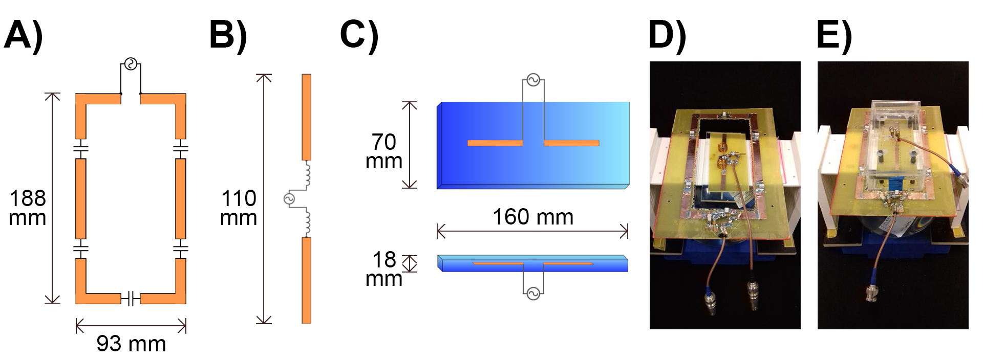
Electromagnetic field simulations in a spherical phantom (radius=90mm, εr=50.6, σ=0.66S/m) using Sim4Life (Sim4Life,Zurich) were carried out for an inductively-shortened dipole antenna (Ind), a dielectrically-shortened (D2O,εr=80) dipole antenna (Diel) and their respective combinations with a loop element (Comb1,Comb2 - Fig.1). Copper width was 10 mm (loop) and 5 mm (dipole). The dielectric block geometry was chosen, so that quasi-transverse electric TE11δz mode could be excited5. All of the four configurations were tuned to 297.2 MHz and matched to 50 Ω using standard capacitive tuning/matching network at 5-mm distance from the phantom. Two additional scenarios for each configuration were investigated in which the distance between the phantom and the elements was increased up to 20 and 30 mm, respectively (no additional tuning and matching was performed after changing the distance). Two transmit/receive switches (MR CoilTech,UK) and a 1:2 power divider (MRI.TOOLS,Germany) were used to interface the Comb1 and Comb 2 to a 7T MR scanner (Magnetom, Siemens). MR experiments in a spherical phantom were conducted using a two-dimensional (2D) gradient-echo sequence: TR/TE=8.6/4.0ms, Nslices=10, slice thickness=3.0 mm, Navg=10, FOV=250x250mm2, transmit voltage=7.9V (reference 50V). The SNR maps were derived by dividing the signal intensity maps by standard deviation of the noise in the backgroundResults
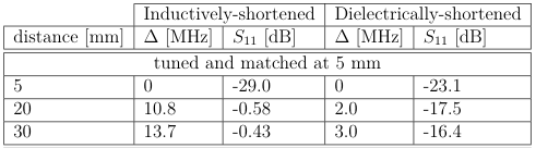
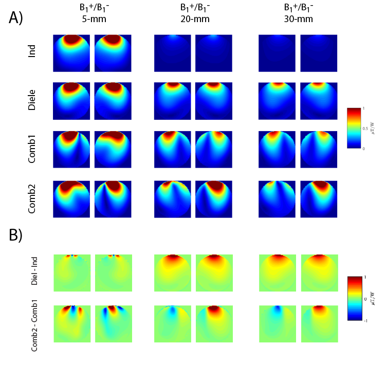
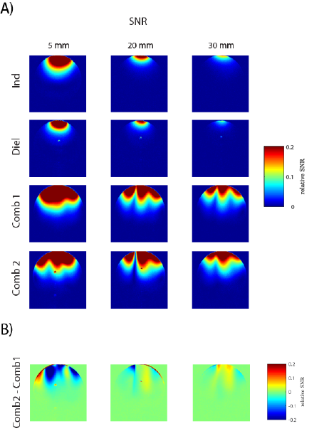
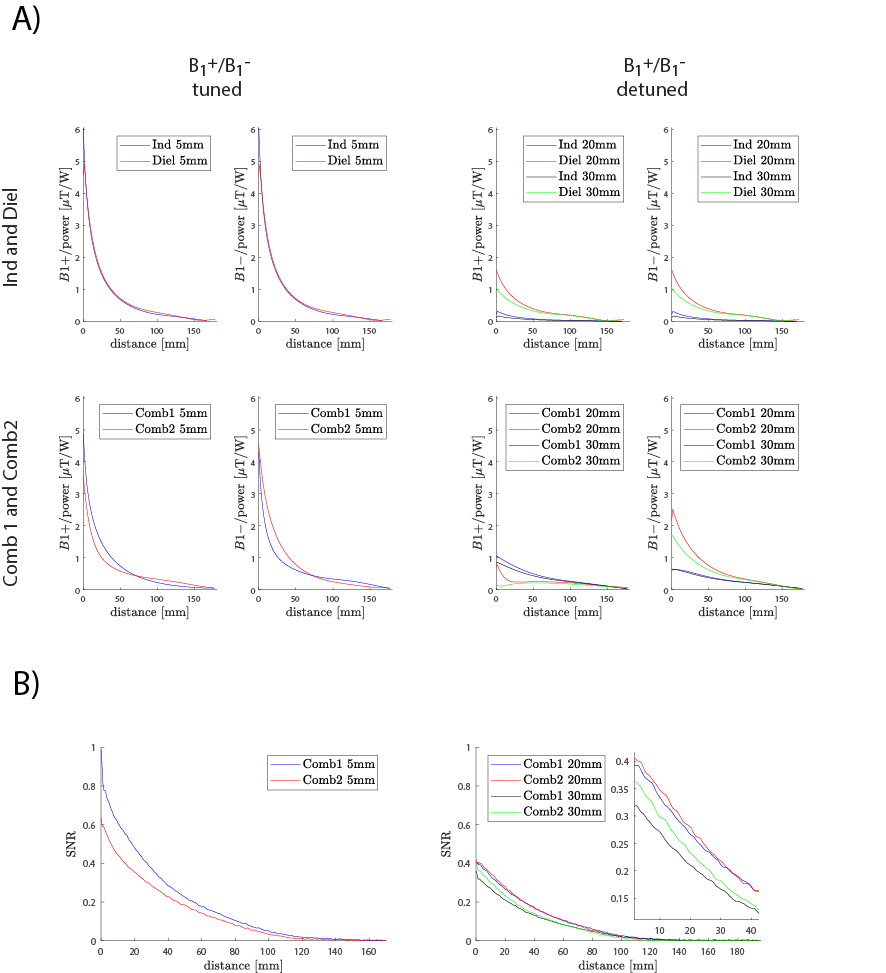
To investigate the coupling between the inductively- and dielectrically-shortened dipole antenna and the spherical phantom, the reflection coefficient (S11) was measured for three different distances: 5, 20 and 30 mm (Fig.2). It was found that the inductively-shortened dipole antenna detuned by 10.8 MHz (for 20 mm) and 13.7 MHz (for 30 mm). To compare transmit (B1+) and receive (B1-) field distributions in the spherical phantom for all of the elements and their combinations, electromagnetic field simulations were performed (Fig.3). Both of the loop/dipole combinations showed significantly different transmit/receive field (B1+/B1-) and Comb2 provided B1- gains when compared with Comb1 (especially for the detuned case – Fig.3b,5a). To estimate the differences in SNR between all configurations, MR phantom experiments were conducted (Fig.4). It was found that for the distances of 20 and 30 mm, Comb2 provided SNR gains in particular regions of the spherical phantom (Fig.4b,5a).Discussion and Conclusion
This work demonstrates for the first time that using a dielectric block (εr=80) to shorten dipole antenna can be a promising alternative for an inductively-shortened dipole antenna in the context of loop-dipole combination for human brain MRI at 7T. In clinical settings, the distance between receive elements of an array and the head of a volunteer is usually not constant. Our results indicate that dielectrically-shortened dipole antenna is significantly less sensitive to loading when compared with its inductively-shortened counterpart which can detune by almost 14 MHz (Tab.1). This detuning effect has a great impact on transmit and receive field profiles and our simulations showed that in such a scenario the dielectrically-shortened dipole antenna can provide higher B1- in particular regions of the spherical phantom (Fig.3b,5a). Preliminary results obtained from phantom experiments showed that the combination of the loop and dielectrically-shortened dipole antenna can provide SNR gains for the distance of 20 and 30 mm when compared with the inductively-shortened dipole antenna (Fig.4b,5b). Even though our phantom experiments showed that inductively-shortened dipole antenna performed better in terms of SNR when it was perfectly tuned to 297.2 MHz and matched to 50Ω, our experiments remain to be fully confirmed: To better investigate the expected SNR gain for the combination of the loop and the dielectrically-shortened dipole antenna (SNR~B1-/√P, see Fig.3), the effect of different B1+ distributions for both loop/dipole antenna combinations would have to be excluded from the experiments. This could be achieved using a separate transmit-only element for both combinations. We also anticipate using ceramic blocks instead of D2O to improve our prototype. Note that εr of the block used in our study was not optimized and further improvements by using a higher εr can be potentially achieved. Using higher εr can also result in additional size reductions, and ultimately moving the antenna closer to the sample (the distance between the dipole antenna and the bottom of the dielectric block in the current prototype is 10 mm).Acknowledgements
We acknowledge access to the facilities and expertise of the CIBM Center for Biomedical Imaging, a Swiss research center of excellence founded and supported by Lausanne University Hospital (CHUV), University of Lausanne (UNIL), Ecole polytechnique fédérale de Lausanne (EPFL), University of Geneva (UNIGE) and Geneva University Hospitals (HUG).References
1. Raaijmakers A, et al. The fractionated dipole antenna: A new antenna for body imaging at 7 Tesla. Magn Reson Med (2016).
2. Erturk A, et al. 16‐channel combined loop‐dipole transceiver array for 7 Tesla body MRI. Magn Reson Med (2017).
3. Lattanzi R et al Approaching ultimate intrinsic signal-to-noise ratio with loop and dipole antennas. Magn Reson Med (2018).
4. Winter L, et al. Design and Evaluation of a Hybrid Radiofrequency Applicator for Magnetic Resonance Imaging and RF Induced Hyperthermia: Electromagnetic Field Simulations up to 14.0 Tesla and Proof-of-Concept at 7.0 Tesla. Plos One (2013).
5. Wenz D and Gruetter R Dielectrically-Shortened Dipole Antennas for MRI at 7.0 T: Thick or Thin? Proc. Intl. Soc. Mag. Reson. Med. 28 (2020).
6. Zhang B, et al. 29-channel receive-only dense dipole head array for 7T MRI. International Conference on Electromagnetics in Advanced Applications (2017).
7. Clement J, et al. A combined 32-channel receive-loops/8-channel transmit-dipoles coil array for whole-brain MR imaging at 7T Magn Reson Med (2019).
Figures