1422
A Novel High Density 32-channel Sleeve Antenna Receiver Array for the Human Head Imaging at 10.5 T1Center for Magnetic Resonance Research, Minneapolis, MN, United States, 2Center for Information and Neural Networks, Osaka, Japan
Synopsis
We designed an elliptically arranged novel 32-channel Sleeve antenna receiver array for human whole brain imaging at 10.5 tesla. To demonstrate the signal-to-noise ratio (SNR) performance of this array, we evaluated and compared it with a standard 32-channel loop receiver array.
Introduction
Curl-free current modes make significant and dominant contributions to the ultimate intrinsic signal-to-noise ratio (UISNR) in the center of larger object at ultra-high frequencies (UHF)1. At UHF of 447MHz/ 10.5 tesla (T), radiative antenna elements, such as dipoles, are predicted to yield closer to optimal coil performance in curl-free current modes compared to loop elements2. Additionally, with increased frequency parallel imaging performance is accelerated3 and increase in sample noise domination supports higher channel count multi-element receivers with smaller individual resonant elements for improved SNR4. However, building densely packed array receivers based on dipole antenna becomes more difficult 5 in part due to the interaction of the dipole with the coaxial feed cable, which typically has to be routed in parallel with one leg of the dipole antenna. Combined with the interactions between coaxial cables of the receiver array in the transmitter array, this can change field patterns and degrade the antenna performance. The structure of a sleeve antenna 6,7, on the other hand, closely resembles a dipole antenna structure except with one important difference: the sleeve antenna array has a more advantageous end-fed structure which integrates the coaxial feed cable into the antenna and supports closer fitting radiative elements. To investigate this, we built a 32-channel sleeve antenna receiver head array and compared with a classic 32-channel loop receiver head array8 at 10.5 T.Methods
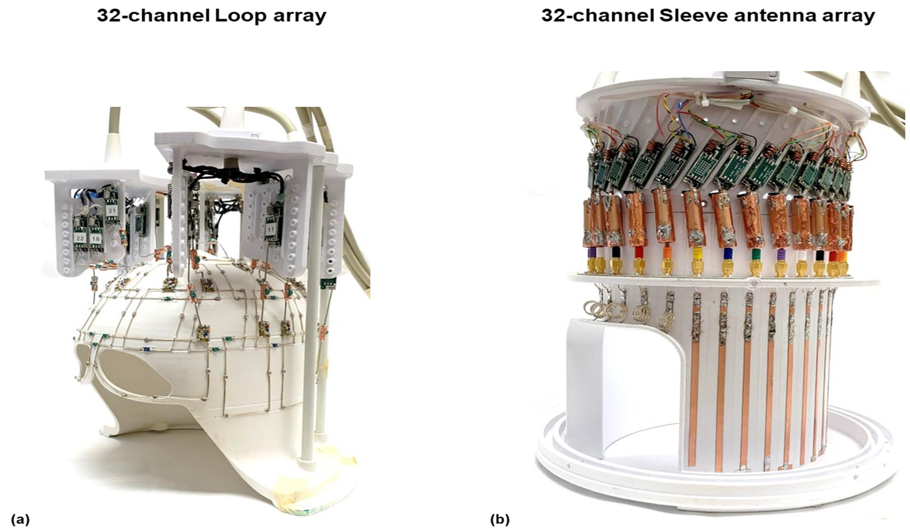
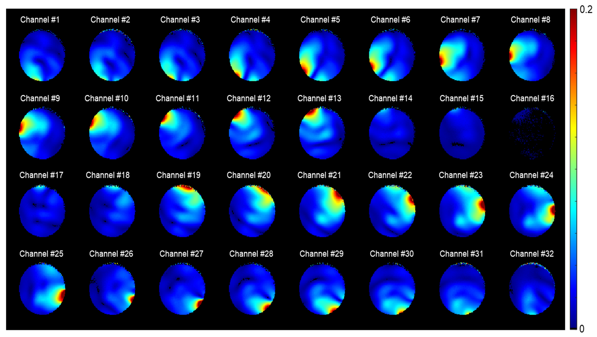
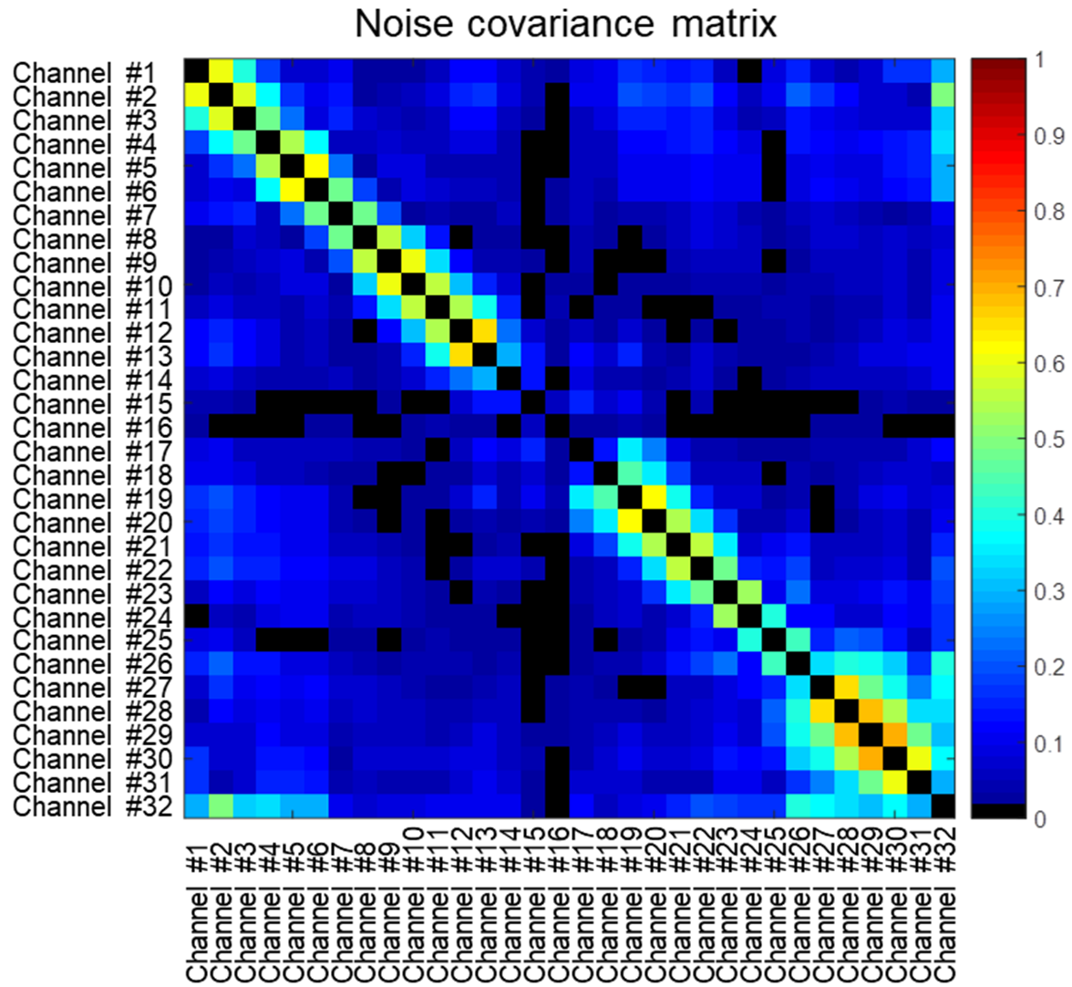
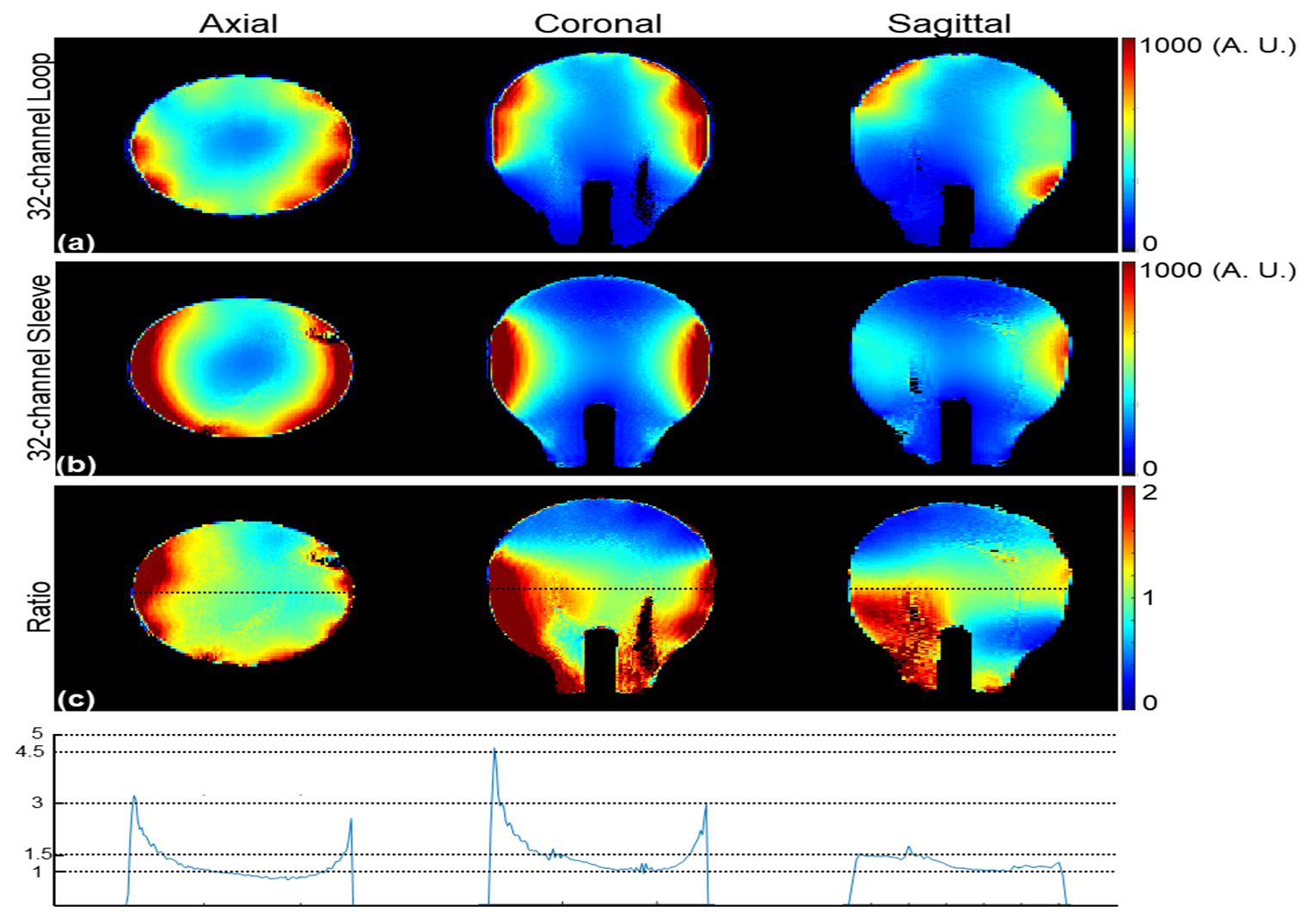
Fig. 1 shows both 32-channel receiver arrays which were mounted on polyethylene terephthalate glycol-modified (PETG) prototype 3D printed housing designs. The 32-channel sleeve antenna array dimensions are: 19 cm × 22.6 cm with azimuthally arranged 32 individual elements tightly spaced at 1.5 cm apart. The length of 27 sleeve antenna elements is approximately 20 cm. Five shorter (5 cm) elements with inductors for resonance are positioned over the forehead. The length of individual sleeve antenna elements was adjusted +/- 0.5 cm for fine tuning. Floating cable traps were used for each sleeve antenna element 7,9,10. The 32-channel sleeve antenna array was compared to a loop array mounted on a close-fitting 3D-printed head former with similar overall inner dimensions but with a conformal fit to the top of the head. Both arrays fit into a 16-channel loop transmitter consisting of an array of sixteen individual 10 × 10 cm2 loop coils arranged in two rows of eight elements11. All detuning and preamplifier decoupling were measured in bench measurements using a 16-channel network analyzer (ZNBT8, Rohde & Schwarz, Munich, Germany). All imaging experiments were performed at 10.5 T. Noise covariance of the 32-channel sleeve antenna array was obtained in Fig. 2. Fig. 3 shows the experimentally acquired individual receiver field maps of the 32-channel sleeve antenna array. A standard proton density-weighted gradient echo (GRE) sequence (TR = 4000 ms, TE = 3 ms, TA = 7:48 minutes, nominal flip angle = 70°, FOV = 354 × 354 and resolution = 1.5 mm × 1.5 mm × 3 mm acquired) was used with a human head shaped phantom (conductivity of 0.69 S/m and the relative permittivity of 49) at the isocenter of the magnet. In Fig. 4, the iSNR maps were calculated from the GRE images by reconstructing the relaxed images in SNR units and correcting for locally varying excitation from separately measured flip angle maps. 12. For quantitative comparisons, the ratio of SNR between the 32-channel sleeve antenna array over the 32-channel loop array were obtained and is displayed in Fig. 4c. The profiles at the isocenter of the phantom are displayed in Fig. 4d.Results
As shown in Fig. 2, noise correlation matrices with the elements further away from each other is in the range of 0.1. However, due to the very tight spacing there were coil pairs that displayed significantly higher (up to 0.69) near-neighbor correlations. As expected, the SNR performance in the superior part of the phantom with the 32-channel sleeve antenna array was lower since the elements are further away from the head phantom compared to the loop array. This results in up to 50 % lower iSNR at the top of the head. However, as observed in Fig. 4c, the new 32-channel sleeve antenna array outperformed the loop array in the lower and central part of the phantom. Here the sleeve antenna array shows up to 4-fold higher peripheral iSNR and about 15 % higher iSNR in the central area of the phantom.Discussion & Conclusion
The structure of a sleeve antenna array, in contrast to classical dipole, does not require parallel alignments of one antenna legs with the coaxial feed cables. This, along with preamplifier current suppression, allowed for about 2-fold denser azimuthal sleeve antennas alignment compared to dipole antennas. Our results indicate that a 32-channel sleeve antenna array can achieve superior SNR in many brain areas compared to a loop array and will thus be a suitable candidate for human MRI at 10.5 T. In the future, we plan to modify the sleeve antenna former to support closer fit of a limited number of sleeve elements to the superior part of the brain and in this way attempt to recover some of the SNR loss in that region.Acknowledgements
NIH-U01-EB025144, NIH-S10-RR029672, NIH-BTRC-P41-EB027061 and NIH-P30-NS076408References
1 Lattanzi, R. et al. Approaching ultimate intrinsic signal‐to‐noise ratio with loop and dipole antennas. Magnetic resonance in medicine 79, 1789-1803 (2018).
2 Pfrommer, A. & Henning, A. The ultimate intrinsic signal‐to‐noise ratio of loop‐and dipole‐like current patterns in a realistic human head model. Magn Reson Med 80, 2122-2138 (2018).
3 Wiesinger, F. et al. Parallel imaging performance as a function of field strength - An experimental investigation using electrodynamic scaling. Magnetic Resonance in Medicine 52, 953-964 (2004).
4 Keil, B. et al. A 64-channel 3T array coil for accelerated brain MRI. Magn Reson Med 70, 248-258, doi:10.1002/mrm.24427 (2013).
5 Zhang, B. et al. in 2017 International Conference on Electromagnetics in Advanced Applications (ICEAA). 1624-1627 (IEEE).
6 King, R. Asymmetrically Driven Antennas and the Sleeve Dipole. P Ire 38, 1154-1164, doi:Doi 10.1109/Jrproc.1950.233110 (1950).
7 Stutzman, W. L. & Thiele, G. A. Antenna theory and design. (John Wiley & Sons, 2012).
8 Tavaf, N. et al. A Self-Decoupled 32 Channel Receive Array for Human Brain Magnetic Resonance Imaging at 10.5 T. arXiv preprint arXiv:2009.07163 (2020).
9 Kissick, W. A., Ingram, W. J., Vanderau, J. M., Jennings, R. D. & Ellison, S. E. Antenna System Guide. (National Law Enforcement and Corrections Technology Center, Rockville, MD, USA, 2001).
10 Seeber, D., Jevtic, J. & Menon, A. Floating shield current suppression trap. Concepts in Magnetic Resonance Part B: Magnetic Resonance Engineering: An Educational Journal 21, 26-31 (2004).
11 Shajan, G., M. Kozlov, J. Hoffmann, R. Turner, K. Scheffler, and R. Pohmann. A 16‐channel dual‐row transmit array in combination with a 31‐element receive array for human brain imaging at 9.4 T. Magn Reson Med 71, 870-879 (2014).
12 Kellman, P. & McVeigh, E. R. Image reconstruction in SNR units: a general method for SNR measurement. Magn Reson Med 54, 1439-1447 (2005)
Figures