1418
Is it feasible to Make More Effective Use of Finite RF Power Resources in pTx Systems Using a Coupling Matrix?1Biomedical Engineering Department, School of Biomedical Engineering and Imaging Sciences, King's College London, London, United Kingdom, 2Centre for the Developing Brain, School of Biomedical Engineering and Imaging Sciences, King's College London, London, United Kingdom
Synopsis
Parallel transmit using equal numbers of RF power amplifiers and coil elements has emerged as a common way to improve the homogeneity of the transmit field through RF shimming. When performing RF shimming, in many cases the magnitude of the transmit field is limited by the maximum power limit of a single RF amplifier. We propose networks that can be used to share power between transmit channels, increasing the maximum transmit field. These networks are shown to provide substantial flexibility in RF power allocation for certain conditions on the relative phases of the channels.
Introduction
In MRI, it is desirable to have a homogeneous transmit RF magnetic field (B1+). RF shimming and other parallel transmit (pTx) techniques use multiple transmit elements to improve B1+ homogeneity as well as to accelerate the application of complex RF pulses1. Presently, the most common configuration for a parallel transmit system has a set of identical RF power amplifiers (RFPAs), one for each transmit element2, although a number of studies have explored how to reduce the number of amplifiers required3,4. Although pTx coils often have a high degree of symmetry, the power required from the transmit channels is often uneven. Thus, although each of the RFPAs is generally specified to produce the same maximum amount of power, only a small number may operate near their rated power limit, limiting maximum B1+. A method to flexibly share power between transmit channels could ease this constraint. This work is an initial investigation into candidate networks to connect N amplifiers to N coil elements to achieve efficient power sharing. Compared to the standard direct connection configuration, a favorable network would deliver equal or greater maximum total power to the coil array when an arbitrary RF shim is demanded.Theory/Methods
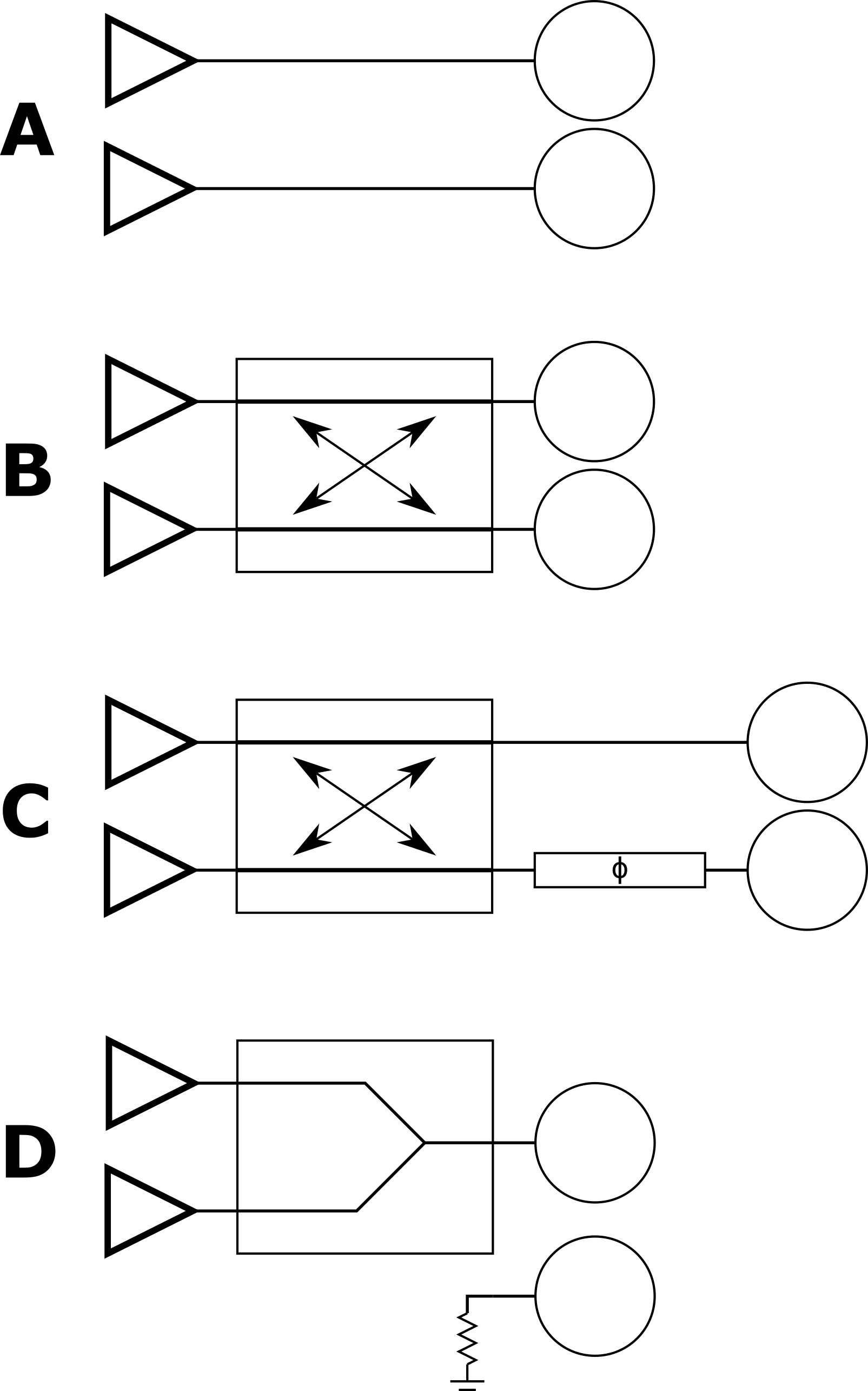
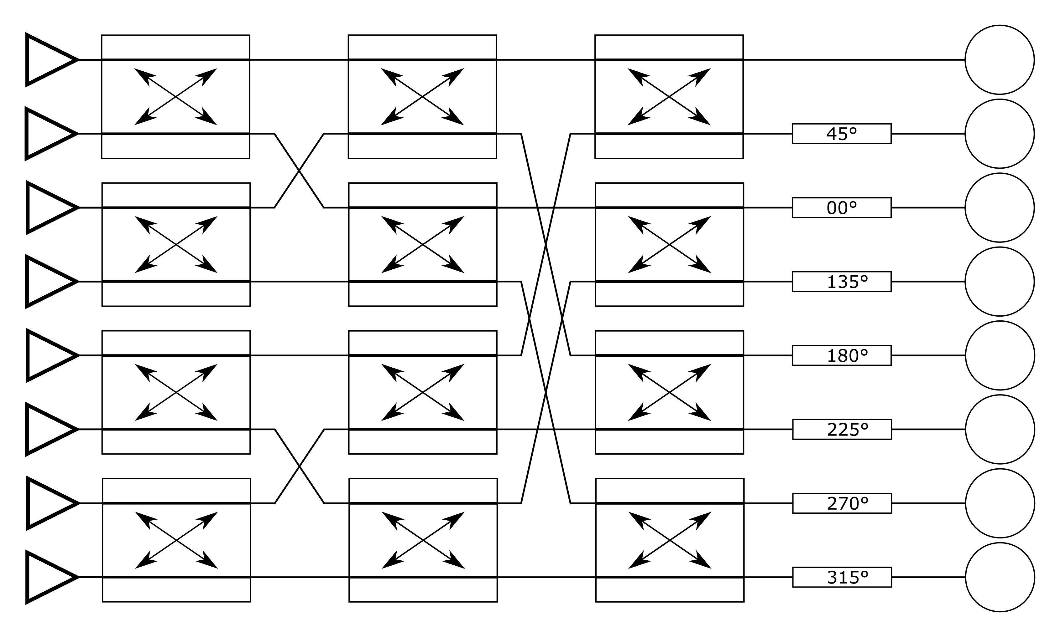
Figure 1 shows four candidate networks that can be used to interface two transmit coils to two RFPAs. A is the present default. B uses a 90° hybrid coupler to share the power of two RFPAs between two transmit coils. C adds a phase shifter to B to allow for an arbitrary optimal phase relationship between the two coils. D is a trivial alternative to complement A, in which a Wilkinson power combiner sums the outputs of two RFPAs while leaving the second coil unexcited.As with Butler matrices, hybrid couplers can be used in cascade for systems with more channels. Figure 2 shows a candidate three-layer network for eight transmit channels such that uniform, in-phase excitation produces eight outputs separated by 45° to achieve a circularly polarized mode with a cylindrical array.
Although the proposed networks promise flexible distribution of power, they all have limitations. Specifically, certain relative phases of the output channels have a lower output power limit than a conventional straight-through network. To investigate this the proposed 2 and 8-channel networks were simulated in Matlab to allow the calculation of the maximum power a coil could receive for a specified network and shim. The relationship between the shim (C) and the amplifier outputs (A) is defined by T.
$$C = TA$$
T for the two-channel network is derived from the behavior of the 90° hybrid coupler which is cascaded for larger networks5. To specify the amplifier drives to a achieve a given coil shim, equation 1 is inverted.
Results
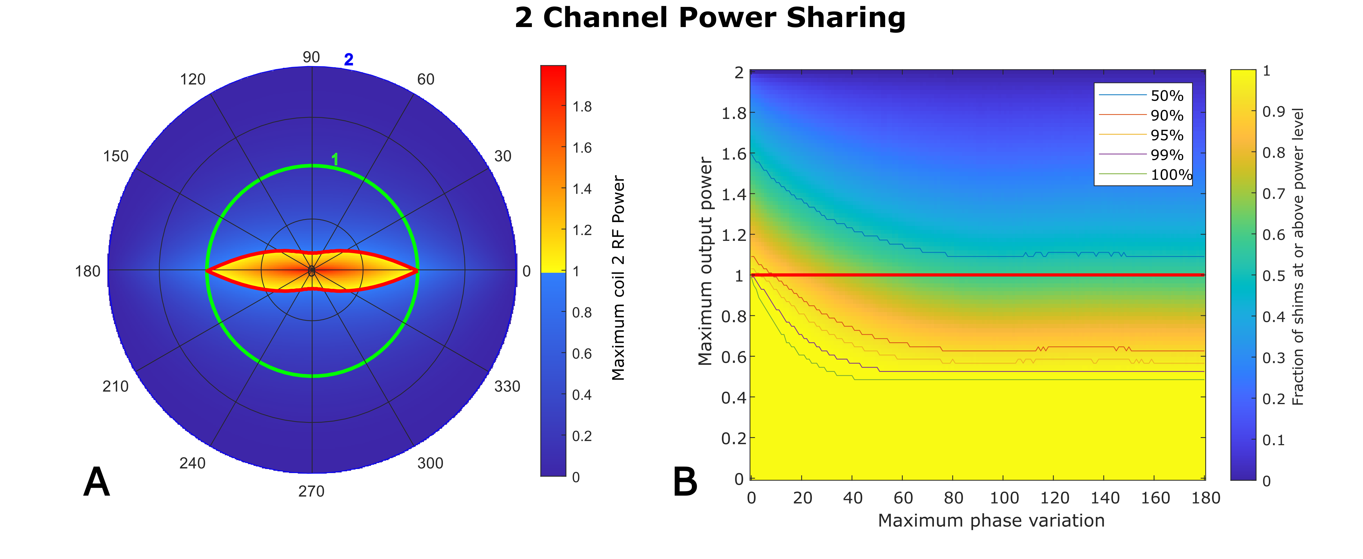
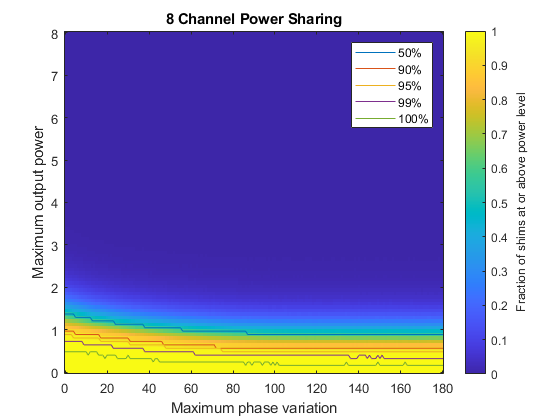
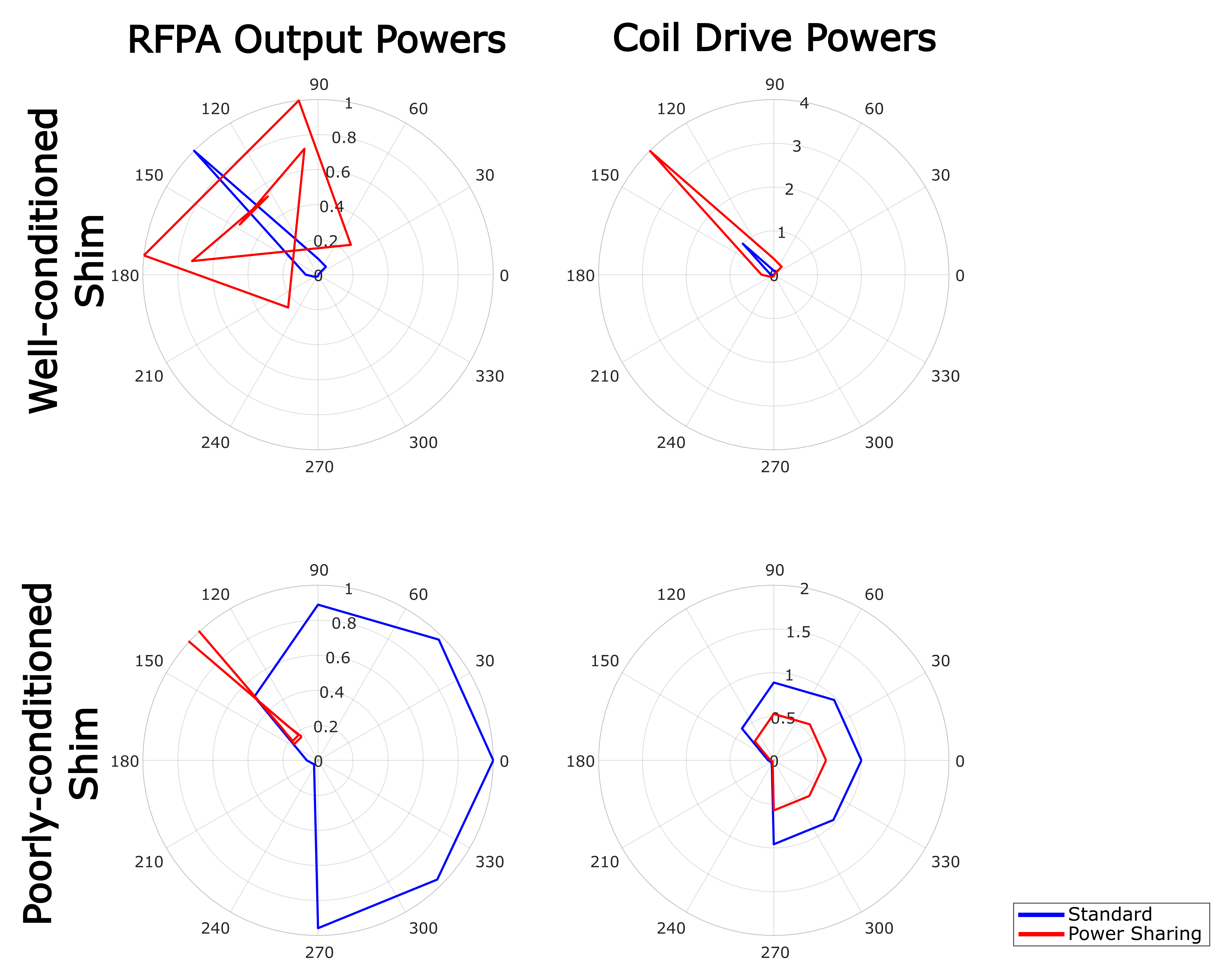
Figure 3 shows results for network B displayed on a polar plot with power from coli one as a radial distance and power from coil 2 as a color, both ranging from 0 to 2. Best performance occurs when the relative phase is close to 0° or 180°.For higher channel count networks, the equivalent of figure 3 would be a hypersphere, which is challenging to visualize. To explore system performance across a wide range of conditions we calculate the ratio of the max power delivered through the network to the max power achievable with direct connection for 100,000 random shim settings using flat distributions of amplitude (0 to 1) and phase deviation from quadrature (-θmax to θmax). Noting that in the two-channel case, performance depends strongly on the relative phase, we vary θmax from 0 to 180, and calculate the fraction of random shims for which the power sharing network delivers more power than the straight-through configuration (Figures 3 and 4). Although the 8-channel network can achieve a factor 8 gain, this is only accessible for a few favorable shim settings. Figure 5 shows two explicit shim examples. In the top case, the network in figure 2 can achieve a 4-fold power gain, whereas in the bottom case the maximum available power is lower than can be achieved by direct connections. In general, only modest gains can be achieved for a wide range of shims, and the 2-channel network shows a more favorable performance in this regime, suggesting that driving coils in pairs could be a more efficient approach.
Conclusion
Enabling sharing power between parallel RF transmit channels could allow existing systems to produce a higher maximum power with the amplifiers they already have. Where RF shims fall within a narrow range of relative phases, power sharing can be highly effective. Adding a variable phase shifter between the power sharing network and the coil elements would increase flexibility.The two-channel network provides an advantage over a larger range of phases than the larger network in figure 2 but is not capable of producing as large of a gain in maximum power.
Using power coupling matrices has the potential to allow an increase in the maximum power that a set of pTx RFPAs can deliver with a given maximum single-amplifier power. By carefully selecting the coils to pair and phase-shifts to include, it could be feasible to increase pTx system performance without increasing RFPA specifications.
Acknowledgements
The authors gratefully acknowledge core funding from the Wellcome/EPSRC Centre for Medical Engineering [WT203148/Z/16/Z] and by the National Institute for Health Research (NIHR) Biomedical Research Centre based at Guy’s and St Thomas’ NHS Foundation Trust and King’s College London and/or the NIHR Clinical Research Facility. The views expressed are those of the author(s) and not necessarily those of the NHS, the NIHR or the Department of Health and Social Care.References
1Zhu Y. Parallel excitation with an array of transmit coils. Magn. Reson. Med. 2004; 51:775–784.
2Orzada S, Solbach K, Gratz M, et al. A 32-channel parallel transmit system add-on for 7T MRI. PLoS One 2019; 14:e0222452.
3Alagappan, V, Setsompop K, Nistler J et al. A Simplified 16-channel Butler Matrix for Parallel Excitation with the Birdcage Modes at 7T. Proc. 16th Sci. Meet. Int. Soc. Magn. Reson. Med. Toronto, 2008:144.
4Yan X, Cao Z, and Grissom W. A. Ratio-adjustable power splitters for array-compressed parallel transmission. Magn. Reson. Med. 2018; 79:2422–2431.
5Pozar D. Microwave Engineering. 2012:343-347.
Figures