1414
Conformal design of radio-frequency head coil for ultra-high field MRI1University of Pittsburgh, Pittsburgh, PA, United States
Synopsis
In this work, we explore a conformal Tic Tac Toe (TTT) head coil design for ultra-high field MRI. By conforming the antennas to the human head, we can extract better homogeneity allowing for better radiofrequency shimming. The comparison between the traditional TTT design and the conformal TTT design shows expanded coverage, reduction of the coefficient of variation by 0.4% and same intensity for the 16-channel version. The conformal designs are extremely flexible as its advantages can be explored for different configurations and sizes.
Introduction
The Tic-Tac-Toe (TTT) coil design for 7 Tesla (T) magnetic resonance imaging (MRI) is an array of antennas that are highly coupled and load insensitive1-6. Many research clinical studies are using the 16-channel TTT design transmit array (Figure 1a) with 32-channel receive head coil6. The conformal Tic Tac Toe (TTT) head coil design goes a step further by opening the possibility for better placement of the antennas around the head, allowing improvements in the homogeneity, SAR, and power efficiency of the coil, beyond the values currently obtained and flexibility of design. Analysis of multiple conformal designs were conducted to obtain evaluate the efficacy of the conformal TTT model.Methods
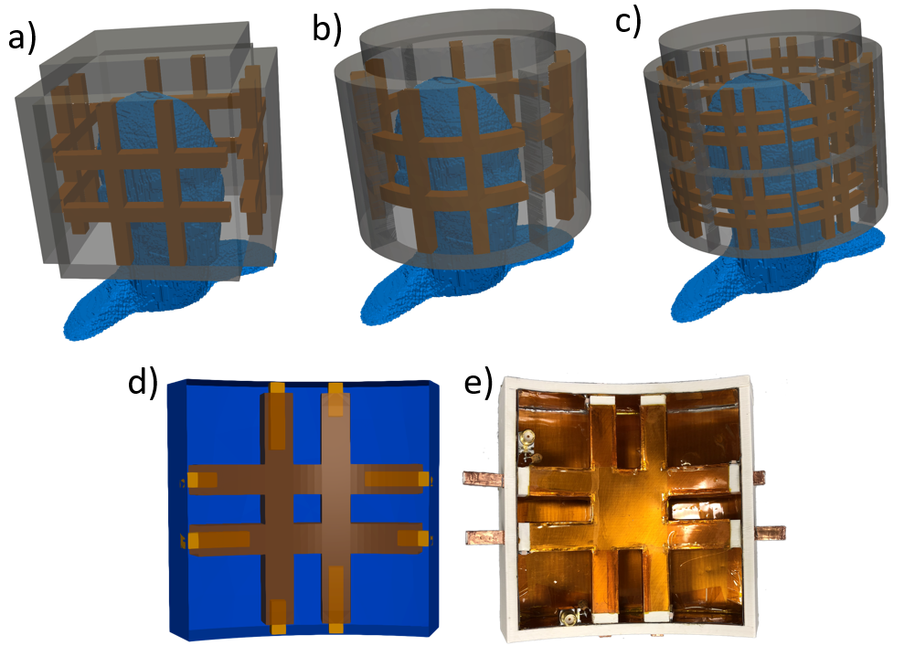
Digitally describing a physical model of a coil is simple for rectangular shapes. For curved and conformal structures and shapes describing a 3D geometry is more complex and time intensive. The creation of an optimized coil design requires several simulations and design iterations. That process can take a long time if any modification requires a manual recreation of each digital point of the 3D geometry. To simplify and speed up the design process, an in-house developed software were used to generate coil models (Figure 1a-d) based on a minimal geometry description such as width, height, and length.To guarantee performance and safety of the new design, simulations of the magnetic and electric field interactions were be performed using an in-house FDTD validated software7 (calculation of the Maxwell’s equations) with a precise transmission line modelling. The resultant circularly polarized 𝐵1+ field, which is the magnetic field that excites the protons, and the Electrical fields, for specific absorption rate (SAR) calculations, are thus obtained8.
The in-house optimization software able to perform nonlinear function minimization for coefficient of variation (CV), maximum over minimum and the coefficient of variation over minimum was used for this work. Additionally, SAR constrains were added to the optimization to guarantee operation within safe limits.
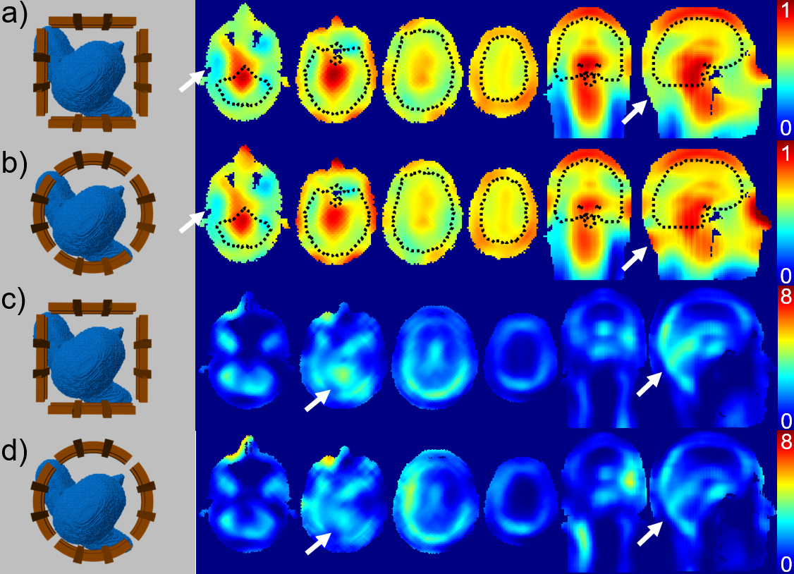
After radiofrequency (RF) shimming9.10 was performed with the optimization for both phase and amplitude. The current TTT design (Figure 1a) was compare with a conformal version (Figure 1b) with the same simulation conditions. The comparison is shown on Figure 2 for both B1+ field and SAR across different axial slices and a coronal and sagittal slice.
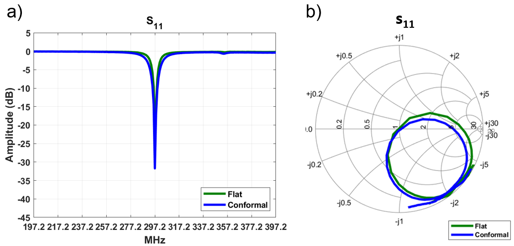
For implementation, a 32-channels conformal coil (Figure 1c) with 4.25 inches panels (Figure 1d) with a total of 16 panels (2 channels per panel) was selected. A single panel was built (Figure 1e) and tested against a similar panel using the traditional flat TTT design using same test condition for both. The magnitude of the reflection coefficient for channel 1 of each panel and its respective smith chart showing the impedance vs. frequency can be seen on Figure 3.
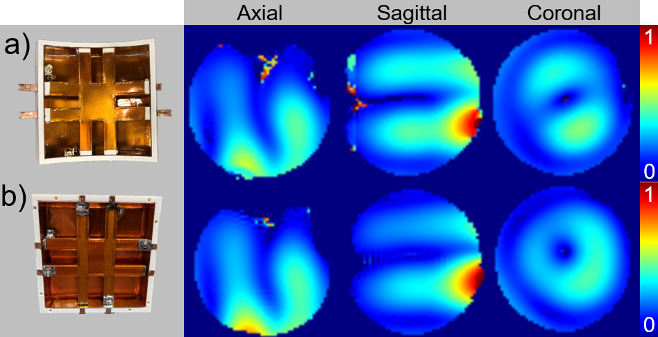
To compare the field distribution of each panel the experimental dataset was calculated from an acquisition using a 7T Siemens MAGNETOM of a Turbo-Flash sequence with 6 different flip-angles variating from 0 to 90 degrees with TE of 1.16ms and TE of 2s, total time of acquisition was 12 minutes. The B1+ field distribution is shown in Figure 4 for all 3 orientations (axial, sagittal and coronal).
Results
The result for the magnetic field (B1) from one sample case of RF shimming shows similar homogeneity and coverage between the regular (Figure 1a) and the conformal 16-channels (Figure 1b) TTT head coils. The CV for the current 16-channel TTT coil (Figure 2a) is 15.6% and the max/min is 2.86 with a mean of 2.71µT/100V. For the 16-channels conformal TTT coil (Figure 2b) further improved the CV to 15.2% and max/min to 2.85 with mean of 2.71µT/100V. These simulations were performed using a 16kW of power for the optimization software.The SAR calculations for both the conformal and regular 16-channels TTT head coils are shown in Figure 2. For the implemented 16-channels TTT head coil (Figure 2c), the peak SAR is 7.44W/Kg/10g and the average SAR is 2.33W/Kg/10g. For the conformal 16-channels TTT head coil (Figure 2d), the peak SAR is 9.04W/Kg/10g and the average SAR is 2.42W/Kg/10g. The higher SAR of the conformal designs were expected since the sources are closer to the surface of the head. By increasing the physical size of the coil, the sources will be far from the head decreasing SAR.
For both homogeneity and SAR, the arrows in Figure 2 show areas with better coverage or lower SAR due to use of a conformal TTT design. That can be validated with the experimental B1+ maps that show similar intensities between both panels (Figure 4), but the distribution of the conformal panel has better penetration and wider coverage. The tuning and matching of the conformal TTT panel match the flat panel (Figure 3) as expected with both having a reflection inferior to -20dB.
Discussion and Conclusion
The new TTT head coil will have 32 channels (Figure 1c) using 2 channels per panel (Figure 1d,e) with a total of 16 panels. The conformal TTT design show better coverage (Figure 4) and therefor allows better RF shimming (Figure 2). Combining with a larger coil size to improve field homogeneity, this new device will be expected to be a significant improvement from past generations.Acknowledgements
This work was supported by NIH R01MH111265 and R01AG063525. The author Tiago Martins was partially supported by the CAPES Foundation, Ministry of Education of Brazil, 88881.128222/2016-01. This research was also supported in part by the University of Pittsburgh Center for Research Computing (CRC) through the resources provided.References
[1] T. S. Ibrahim, Y.-K. Hue, F. E. Boada, and R. Gilbert, “Tic Tac Toe: Highly-Coupled, Load Insensitive Tx/Rx Array and a Quadrature Coil Without Lumped Capacitors,” presented at the 16th International Society of Magnetic Resonance in Medicine Annual Meeting, Toronto, Ontario, Canada, 2008, vol. 16th, p. 438.
[2] J. Kim et al., “Experimental and numerical analysis of B1+ field and SAR with a new transmit array design for 7T breast MRI,” Journal of Magnetic Resonance, vol. 269, pp. 55–64, Aug. 2016.
[3] Tales Santini et al., “64-channel Double-Octagon Tx Head Coil for 7T Imaging,” in International Society for Magnetic Resonance in Medicine, Honolulu, HI, 2017, vol. 25th.
[4] Tales Roberto de Souza Santini, Junghwan Kim, Sossena Wood, Narayanan Krishnamurthy, Shailesh Raval, and Tamer Ibrahim, “A new RF coil for foot and ankle imaging at 7T MRI,” in International Society for Magnetic Resonance in Medicine, Honolulu, HI, 2017, vol. 25th.
[5] S. B. Raval, T. Santini, S. Wood, N. Krishnamurthy, T. Zhao, and T. S. Ibrahim, “In-vivo (8x4) 32-ch Tx-only Body Array for UHF MRI.,” in International Society for Magnetic Resonance in Medicine, Honolulu, HI, 2017, vol. 25th, p. 3.
[6] T. S. Ibrahim, N. Krishnamurthy, S. Wood, S. Raval, and H. Kim, “20-To-8 channel Tx array with 32-channel adjustable receive-only insert for 7T head imaging,” in The 21st International Society of Magnetic Resonance in Medicine Annual Meeting, 2013.
[7] T. S. Ibrahim, A. Kangarlu, and D. W. Chakeress, “Design and performance issues of RF coils utilized in ultra high field MRI: experimental and numerical evaluations,” IEEE Transactions on Biomedical Engineering, vol. 52, no. 7, pp. 1278–1284, Jul. 2005.
[8] T. S. Ibrahim, “Analytical approach to the MR signal,” Magnetic Resonance in Medicine, vol. 54, no. 3, pp. 677–682, Sep. 2005.
[9] T. S. Ibrahim, Y.-K. Hue, and L. Tang, “Understanding and manipulating the RF fields at high field MRI,” NMR in Biomedicine, vol. 22, no. 9, pp. 927–936, 2009.
[10] L. Tang, Y.-K. Hue, and T. S. Ibrahim, “Studies of RF Shimming Techniques with Minimization of RF Power Deposition and Their Associated Temperature Changes,” Concepts Magn Reson Part B Magn Reson Eng, vol. 39B, no. 1, pp. 11–25, Feb. 2011.
Figures