1412
Analysis of preamplifier decoupling effect in MRI coil array with electromagnetic field and RF circuit co-simulation1Vanderbilt University Institute of Imaging Science, Vanderbilt University Medical Center, Nashville, TN, United States, 2Department of Radiology and Radiological Sciences, Vanderbilt University Medical Center, Nashville, TN, United States, 3Advanced Imaging Research Center, University of Texas Southwestern Medical Center, Dallas, TX, United States
Synopsis
Preamplifier decoupling is a standard way of suppressing inter-element inductive coupling in MRI receive arrays. A well-known method to evaluate and optimize RF coils before practical fabrication is to use circuit-level and electromagnetic (EM) field-level simulations. However, to be best of our knowledge, currently there is not a solid method to evaluate the preamp decoupling effect with circuitry and EM field analysis. In this work, we used RF circuit and EM co-simulation4 to evaluate the preamplifier decoupling effect and tested it on the conventional coil (LIC) and the recently introduced high impedance coil (HIC).
Purpose:
Preamplifier decoupling is a standard way of suppressing inter-element crosstalk in MRI receive arrays. The original preamplifier decoupling was mainly used to reduce the coupling among non-adjacent elements in which the geometrically-overlap decoupling1 is not feasible. Recently, a strong trend has been arising to develop advanced preamp decoupling methods for flexible coils. Unlike the original method in Roemer et al1, advanced preamp decoupling methods are aiming at robust decoupling/noise suppression so the overlapping area is not crucial2,3. A well-known method to evaluate and optimize RF coils before practical fabrication is to use circuit-level and electromagnetic (EM) field-level simulations. However, to be best of our knowledge, currently there is not a solid method to evaluate the preamp decoupling effect with circuitry and EM field analysis. In this work, we used RF circuit and EM co-simulation4 to evaluate the preamplifier decoupling effect and tested it on the conventional coil (LIC)1 and the recently introduced high impedance coil (HIC)2.Methods:
Figure 1 showed the schematic drawings of the LIC and HIC. For the LIC, we evaluated two matching strategies, one is the parallel matching strategy with a single matching capacitor Cm, and the other one is the series matching strategy with two series capacitors (Cms) and an intentional small capacitor Cm (referred to as small-Cm LIC). The small Cm is expected to improve the quality factor of the blocking circuit consisting Cm and the preamplifier load5-7. In each case, the coil has a diameter of 78 mm, and was tuned at 128 MHz and matched to 50 Ω.Figure 2 depicted the procedures of the proposed co-simulation approach. First, coils were modeled in an EM simulation (Ansys HFSS) with all lumped elements replaced with 50 Ω. Second, values of tuning and matching capacitors were optimized by minimizing coils’ reflection coefficient (S11) in co-simulation environment (Ansys Designer). Third, the imaginary part of the preamplifier's input impedance was optimized to maximize the preamplifier decoupling. Similar to the practical case8, this was obtained by minimizing the transmission coefficient (S21) of a well-decoupled double-pick-up probe that was placed several centimeters above the coil. By now, the preamplifier decoupling ability can be evaluated in the RF circuit simulator. To further evaluate the SNR performance, the optimized imaginary part and the previously set Re[Zin] were converted to equivalent parallel resistance (Req) and parallel reactance (usually inductance, Leq) and imported into EM simulation. Finally, individual B1- fields and electric (E-) fields were calculated and exported to MATLAB for SNR calculation. Unlike the conventional simulations assuming other coils opened, this simulation method will account for additional noise correlation and SNR loss caused by residual coupling.
Results and Discussions:
Figures 3 showed the preamplifier decoupling effect of the three coils, with Re[Zin] set with 0, 2, 5 and 10 Ω. Similar to the practical case, the preamplifier decoupling effect was evaluated as the resonate response difference (ΔS21) between the 50 Ω termination and the preamplifier input impedance termination8. For Re[Zin] = 0 Ω, almost perfect decoupling can be achieved, with ΔS21 of ~58 dB. As Re[Zin] increases, ΔS21 of LIC coil with normal Cm dropped dramatically, with ΔS21=25/18/15 dB when Re[Zin] =2/5/10 Ω respectively. On the contrary, both the HIC coil and the small-Cm LIC varied much less when the Re[Zin] changed. For the HIC, the ΔS21=50/45/43 dB when Re[Zin] =2/5/10 Ω. For the small-Cm LIC coil, the ΔS21=56/53/50 dB when Re[Zin] =2/5/10 Ω. It should be noted that choosing extremely small Cm in the series matching circuit of the LIC will induce a dipole mode to the loop coil, making the current distribution along conductors less uniform than that of the typical LIC coil.Figure 4 showed the B1- field distortion due to non-perfect preamplifier decoupling. For each case, two coils were placed side-by-side with 2 mm apart. The coil on the right was driven with 1-watt power while the coil on the left was terminated with Req and Leq. These B1- fields were also compared to the baseline B1- fields from a single coil (without the left coil, left column in Figure 4). The B1- results were consistent with the S21 in Figure 3. For the typical LIC coil, the B1- distortion was highly dependent on the Re[Zin]. For the HIC and small-Cm LIC coils, however, the original B1- field can be maintained even with Re[Zin] = 10 Ω.
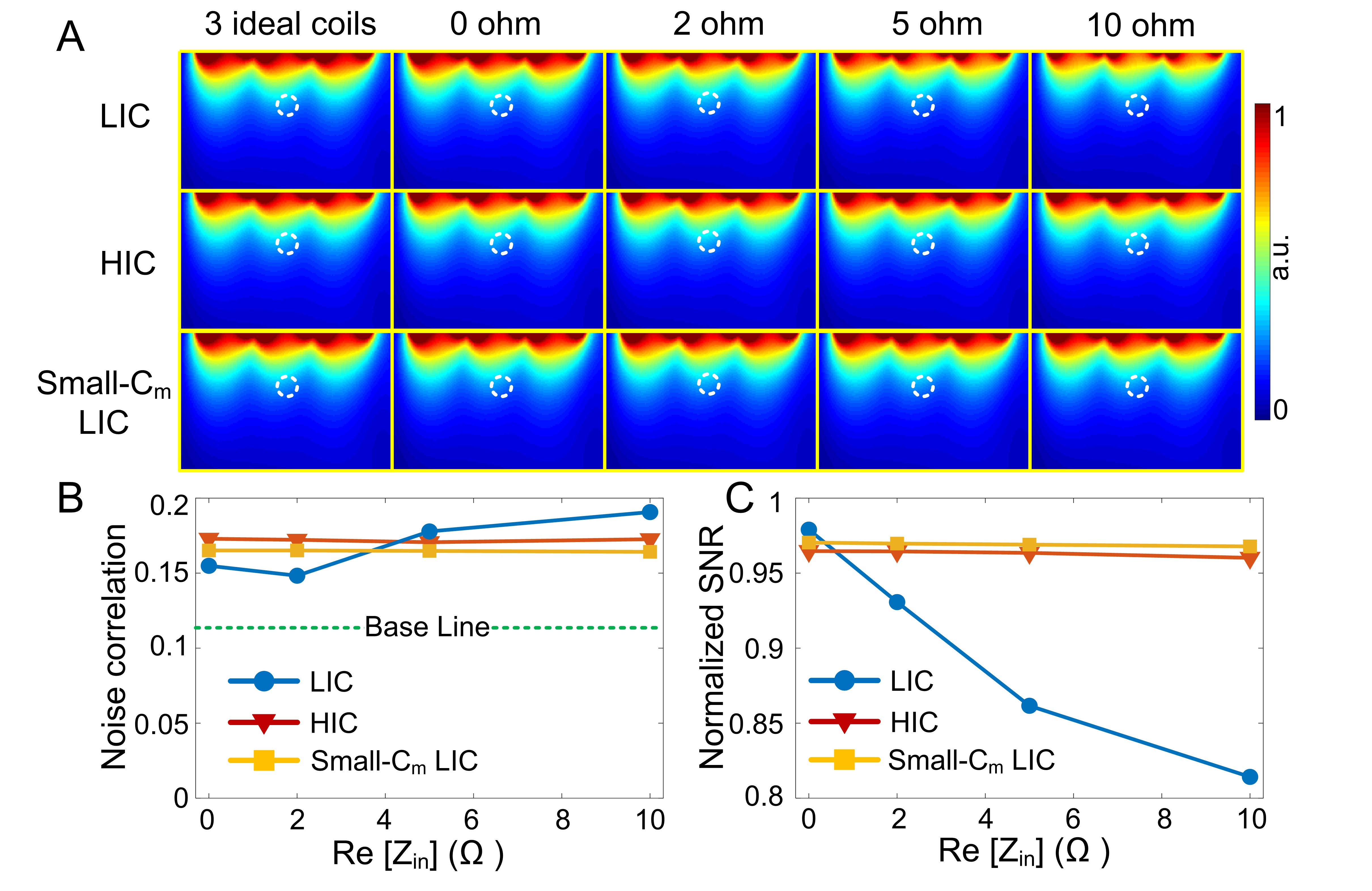
Figure 5A showed the normalized SNR maps from three side-by-side coils. Figure 5B plotted the average noise correlation of neighbor coils (i.e., left-middle and right-middle coils). Figure 5C plotted normalized SNR values in an 40-mm-deep region that is directly under the middle coil. The SNR result was also consistent with simulated decoupling (ΔS21) and B1- results.
Conclusion:
We proposed an RF circuit and EM field co-simulation method that can evaluate the preamplifier decoupling in terms of the resonate response difference, receive sensitivity (B1-), and array SNR.Acknowledgements
No acknowledgement found.References
1. Roemer PB, Edelstein WA, Hayes CE, Souza SP, Mueller OM. The NMR phased array. Magnetic resonance in medicine. 1990 Nov;16(2):192-225.
2. Zhang B, Sodickson DK, Cloos MA. A high-impedance detector-array glove for magnetic resonance imaging of the hand. Nature biomedical engineering. 2018 Aug;2(8):570-7.
3. Vasanawala SS, Stormont R, Lindsay S, Grafendorfer T, Cheng JY, Pauly JM, Scott G, Guzman JX, Taracila V, Chirayath D, Robb F. Development and clinical implementation of next generation very light weight and extremely flexible receiver arrays for pediatric mri. arXiv preprint arXiv:1705.00224. 2017 Apr 29.
4. Kozlov M, Turner R. Fast MRI coil analysis based on 3-D electromagnetic and RF circuit co-simulation. Journal of magnetic resonance. 2009 Sep 1;200(1):147-52.
5. Zhu H. Imris Inc. Coil decoupling for an RF coil array. United States patent US 8,138,762. 2012 Mar 20.
6. Wiggins GC, Polimeni JR, Potthast A, Schmitt M, Alagappan V, Wald LL. 96‐Channel receive‐only head coil for 3 Tesla: design optimization and evaluation. Magnetic Resonance in Medicine: An Official Journal of the International Society for Magnetic Resonance in Medicine. 2009 Sep;62(3):754-62.
7. Hergt M, Oppelt R, Vester M, Reykowski A, Huber KM, Jahns K, Fischer H. Low noise preamplifier with integrated cable trap. In: Proceedings of the 15th Annual Meeting of ISMRM, Berlin, Germany, 2007 (Abstract 1037).
8. Reykowski A, Wright SM, Porter JR. Design of matching networks for low noise preamplifiers. Magnetic resonance in medicine. 1995 Jun;33(6):848-52.
Figures