1411
Rapid high power transmit-receive switching using a timed cascade of PIN diodes1Institute for Biomedical Engineering, ETH Zurich and University of Zurich, Zürich, Switzerland
Synopsis
For imaging of short-T2 samples often very short excitation pulses are desired, which requires high peak RF power. In this work, a transmit-receive switch is presented that can handle 18kW peak RF power and switches its state in less than 1µs. The novel design uses a timed cascade of anti-parallel PIN diode pairs to achieve this performance.
Introduction
For imaging compounds with very short coherence life times it is of great importance that the excitation pulse is short. This is particularly true for the zero echo time (ZTE) technique, in which the readout gradient is already on during excitation. In this case, the pulse duration determines a k-space gap to be minimized [1-5]. Further, in ZTE the excitation bandwidth must be at least as broad as the acquisition bandwidth, limiting the pulse duration when block pulses are used. Finally, rapid excitation also minimizes relaxation during the pulse.As excitation pulses get shorter, ever-higher RF power is required to still reach optimal flip angles. This imposes steep requirements on the transmit-receive (T/R) switches involved, which must not only handle increasing power, but also switch very fast, equally in the order of microseconds. T/R switches are typically based on PIN diodes, which require strong current pulses to change state rapidly and might overload the RF receive chain by switching transients. To-date, the fastest T/R switching in the kilowatt range has been achieved by symmetrically biasing PIN diodes [6]. With this design, switching in less than 1µs has been accomplished at 2kW peak power. However, emerging modes of ZTE imaging with large bandwidth and flip angle call for still higher RF power [7-8]
In this work, we propose a timed cascade of PIN diodes to overcome current power limits. Using this approach it is shown that sub-microsecond switching can be reconciled with 18kW RF transmission.
Methods
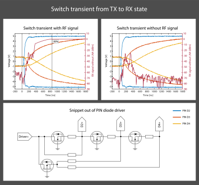
The proposed RF topology is shown in Fig. 1. During RF transmission, all PIN diodes are forward-biased. Towards the receive port, the PIN diodes are successively selected with shorter carrier lifetime and less charge is injected during forward biasing. During reception, the PIN diodes are reverse-biased. The anti-parallel arrangement of each diode pair ensures rough cancelation of any transient voltages. The PIN diode pairs in the receive path are reverse biased in a timed cascade, starting with the one nearest to the TR port. In this way, transient voltage peaks are absorbed by the subsequent PIN diodes, which are not yet reverse-biased when the previous PIN diode stage peaks. Because later stages require less current to reverse-bias rapidly, the final transient peak is sufficiently small to be within the linear range of the utilized low noise amplifier.The PIN diode driver as shown in Fig. 2 is made such that the cascading is passively self-triggered. A later PIN diode stage starts pulling out charge carriers from the intrinsic layer as soon as the previous stage crosses zero Volt biasing. At zero Volts, the majority of charge carriers have been extracted and the PIN diodes change to a high impedance state. This ensures that when a PIN diode stage peaks, the subsequent stage is still conducting RF and thereby catching such voltage peak.
Measurements of the transient response were made with an Agilent Technologies MSO7054A oscilloscope, a R&S SMB 100A signal generator, an Agilent Technologies 81104A pulse-pattern generator and a National Instruments PXIe-5622 16-bit digitizer. Insertion loss and isolation were measured with an Agilent Technologies E5071C network analyzer. To validate the electrical and thermal integrity an Analogic AN8134 18kW amplifier, a R&S FSL spectrum and a Fluke TiS20 were utilized.
Finally, high-bandwidth ZTE imaging with algebraic reconstruction was performed on phantoms and in-vivo using a Philips Achieva 3T scanner with a high-performance insert gradient [9].
Results
At the operation frequency of 128MHz, the insertion loss from the TX to the TR port in the transmit state is -0.25dB and the insulation to the RX port is -76.3dB. In the receive state the insertion loss from the TR port to the RX port is -0.5dB and the insulation towards the TX port is -62.5dB.Fig. 2 shows the cascaded reverse biasing and the switching process. Based on this data, the rise time was assessed at 855ns and the maximum transient voltage is -25.5dBm.
Bench measurements verified that full peak output power of the 18kW amplifier could be applied without losing the integrity of the pulse. Fig. 3 shows, 100W average power with 15kW peak power could be applied without issues.
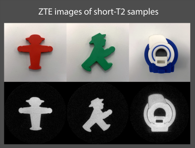
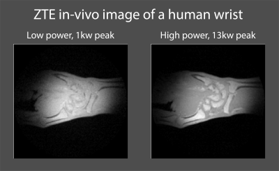
The imaging revealed that ZTE images of short-T2 phantoms, as shown in Fig. 4, exhibit no visible artifacts related to the switching process. Further as shown in Fig. 5, with 13kW peak RF power, better SNR and contrast was achieved in in-vivo ZTE imaging, compared to the more common 1kW.
Discussion and conclution
The presented T/R switch was shown to be able to handle high peak power of 18kW, while maintaining a switching time below 1µs. These capabilities present will facilitate imaging of materials with ever shorter T2 samples such as myelin or collagen [8,10].Rapid switching was accomplished with a timed cascade. The passive self-triggered reverse bias sequence makes the design not only simple to implement but also robust since it inherently adapts to alterations in voltage dynamics.
To further reduce the switching time of the current implementation, higher reverse voltage could be applied and the related increase in the transient voltage peak could be resolved by an additional PIN diode stage in the cascade.
Acknowledgements
No acknowledgement found.References
[1] Weiger, M., Pruessmann, K.P. and Hennel, F. (2011), MRI with zero echo time: Hard versus sweep pulse excitation. Magn. Reson. Med., 66: 379-389. https://doi.org/10.1002/mrm.22799
[2] Weiger M, Pruessmann KP. MRI with Zero Echo Time. eMagRes. 2012;1:311–322.
[3] Grodzki DM, Jakob PM, Heismann B. Ultrashort echo time imaging using pointwise encoding time reduction with radial acquisition (PETRA). Magnetic Resonance in Medicine. 2012;67:510–518.
[4] Wu Y, Dai G, Ackerman JL, Hrovat MI, Glimcher MJ, Snyder BD, Nazarian A, Chesler D a. Water- and fat-suppressed proton projection MRI (WASPI) of rat femur bone. Magnetic resonance in medicine. 2007;57:554–67.
[5] R.N. Froidevaux, M.B. Rösler, D.O. Brunner, M. Weiger, K.P. Pruessmann, HYFI: hybrid filling of the dead-time gap for faster zero echo time imaging, Proceedings of the 27th Annual Meeting of ISMRM, Canada, Montreal (2019), p. 943
[6] Brunner, D.O., Furrer, L., Weiger, M., Baumberger, W., Schmid, T., Reber, J., Dietrich, B.E., Wilm, B.J., Froidevaux, R., Pruessmann, K.P., 2016. Symmetrically biased T/R switches for NMR and MRI with microsecond dead time. J. Magn. Reson. https://doi.org/10.1016/j.jmr.2015.12.016
[7] Froidevaux, R, Weiger, M, Rösler, MB, et al. High‐resolution short‐T2 MRI using a high‐performance gradient. Magn Reson Med. 2020; 84: 1933– 1946. https://doi.org/10.1002/mrm.28254
[8] Markus Weiger, Romain Froidevaux, Emily Louise Baadsvik, David Otto Brunner, Manuela Barbara Rösler, Klaas Paul Pruessmann, Advances in MRI of the myelin bilayer, NeuroImage, Volume 217, 2020, https://doi.org/10.1016/j.neuroimage.2020.116888.
[9] Weiger, M., Overweg, J., Rösler, M.B., Froidevaux, R., Hennel, F., Wilm, B.J., Penn, A., Sturzenegger, U., Schuth, W., Mathlener, M., Borgo, M., Börnert, P., Leussler, C., Luechinger, R., Dietrich, B.E., Reber, J., Brunner, D.O., Schmid, T., Vionnet, L. and Pruessmann, K.P. (2018), A high‐performance gradient insert for rapid and short‐T2 imaging at full duty cycle. Magn. Reson. Med, 79: 3256-3266. https://doi.org/10.1002/mrm.26954
[10] Baadsvik, E.L., Weiger, M., Froidevaux, R., Rösler, M.B., Brunner, D.O., Öhrström, L., Rühli, F.J., Eppenberger, P., Pruessmann, K.P., High-resolution MRI of mummified tissues using advanced short-T2 methodology and hardware, (2021) Magnetic Resonance in Medicine, 85 (3), pp. 1481-1492. https://doi.org/10.1002/mrm.28615
Figures

Left: Illustration of the RF topology of the high-power T/R switch. The antiparallel PIN diode pairs are driven in a cascaded way. Towards the RX port, PIN diodes with shorter carrier lifetime are deployed.
Right: Implementation of such an RF topology. In addition, auxiliary circuits and low noise amplifier (LNA) can be seen.

Top row: transient switch behavior when switching from the TX to the RX state. The reverse bias is built up in a cascade, which reduces the transient voltage peaks.
Bottom row: Snippet out of the passive self-triggered PIN diode driver. As long as a PIN diode is still in its low impedance state, it has a forward voltage present, despite bulling a reverse current out of it. When the PIN diode changes to its high impedance state, current is drawn out of the next stage.

