1410
Flexible Tunable Capacitor: A Variable Capacitor for Tuning Flexible/Thermoformed MRI Coils1EECS, UC Berkeley, Berkeley, CA, United States
Synopsis
Recent advances in coil design and fabrication have allowed for flexible and thermoformed coil arrays. However, the weak solder joints and rigid design of traditional variable capacitors used with these coils greatly limit their flexibility. Here, we propose the Flexible Tunable Capacitor (FTC), a high-Q, flexible, easily tunable variable capacitor. This design uses an array of small low-loss parallel plate capacitors adjustable with small step sizes by exploiting series and parallel combinations. This work proposes a basic design that offers a wide range of capacitor values (0.5 pF to 7 pF) suitable for 3T and 7T coils.
Introduction
Basic MRI coil elements consist of loop resonators tuned to the operating frequency of each scanner1. Traditionally, several capacitors are distributed across the resonant loop with some designs employing variable capacitors in order to fine tune the loop. Surface mount variable capacitors offer high quality factor (Q) in a small package and maximize the potential SNR of the received MR signal. Rigid variable capacitors work well for fixed commercial coils; however, recent advancements have allowed for flexible/conformal coils that can be placed as close as possible to the patient, ultimately increasing the SNR2,3. Rigid surface mount variable capacitors become an issue when designing flexible/conformal coils as their compact size and weak solder joints limit the coil’s ability to remain flexible. Solutions to this problem have been proposed by using overlapping traces on screen-printed MRI receiver coils4 or flexible PCB, and ad-hoc scraping off conductive material for tuning. In this work, we present a disciplined Flexible Tunable Capacitor with a small form factor, wide tuning range (0.5 pF to 7 pF), and small step sizes (0.225 pF max). We describe the methodology for designing and fabricating our Flexible Tunable Capacitors and provide RF simulations to demonstrate their performance across the entire tuning range.Methods
An array of parallel plate capacitors can be combined in series and parallel to achieve a wide range of capacitance. Our design is split into three arrays of parallel plate capacitors, forming three different variable capacitors. Figure 1 shows that $$$C_{sa}$$$ and $$$C_{sb}$$$ are connected in series to form $$$C_s$$$. $$$C_s$$$ and $$$C_p$$$ are connected in parallel. The elements within each capacitor array (marked 1-4) are connected in parallel. The entire capacitor is tuned by cutting or soldering the connections between the array elements, which changes the values of $$$C_{sa}$$$, $$$C_{sb}$$$ and $$$C_p$$$.The total capacitance is given by $$$C_{total}=C_{s}+C_{p}$$$ where $$$C_{s}=(C_{sa}^{-1}+C_{sa}^{-1})^{-1}$$$.
$$$C_p$$$ is used for coarse tuning with steps $$$\Delta C_{p} = C_{p}/N_{C_p}$$$, where $$$N_{C_p}$$$ are the number of sub-elements in $$$C_{p}$$$ ($$$N_{C_p}=4$$$ in Figure 1). At the same time, $$$C_s$$$ (through $$$C_{sa}$$$ and $$$C_{sb}$$$) is used for fine-tuning around the $$$C_p$$$ value. This is done by controlling the size of $$$C_{sa}$$$ and $$$C_{sb}$$$, each of which have steps of $$$\Delta C_{sa} = C_{sa}/N_{C_{sa}}$$$ and $$$\Delta C_{sb} = C_{sb}/N_{C_{sb}}$$$, where $$$N_{C_{sa}}$$$ and $$$N_{C_{sb}}$$$ are the number of sub-elements in $$$C_{sa}$$$ and $$$C_{sb}$$$ respectively ($$$N_{C_{sa}}=N_{C_{sb}}=4$$$ in Figure 1). For continuous step sizes, $$$\Delta C_p$$$ should be set to $$$\max C_s - \min C_s $$$
For implementation on flex PCB, DuPont Pyralux AP was used for its low loss properties5. Figure 1b shows the implementation of the board on Pyralux AP. The slotted vias on the ends allow the board to be mounted to thermoformed surfaces without soldering (attached with nylon screws) or with limited soldering. The board was designed with ease of tuning in mind. To tune the capacitance of the board, the exposed traces can be carefully cut to reduce the total capacitance of $$$C_{sa}$$$, $$$C_{sb}$$$, and $$$C_{p}$$$ (Figure 1b). The small traces can also be resoldered to restore the lost connection.
The PCB layout was imported into an RF simulator to measure the capacitance, quality factor, and breakdown of the structure6. To verify that the quality factor reported in simulation matches closely with real life performance, a parallel plate capacitor made from Pyralux was measured in the lab and compared to the simulator.
Results and Discussion
The performance of the simulated Flexible Variable Capacitor is shown in Figures 2 and 3. From Figure 2c, it’s clear that the estimated enumerated range using ideal series and parallel combinations can be matched using the PCB design shown in Figure 1b. In addition to its wide tuning range, the quality factor of the board remains high throughout its entire range for both 3T and 7T. As a result, this design is suitable for achieving a wide tuning range while providing step sizes small enough to tune the center frequency of a coil by a few MHz every step (Figure 2d). The range and step size can be altered by adding more capacitors to each array or by changing the size of $$$\Delta C_s$$$ and $$$\Delta C_p$$$. Some potential issues with this design involve shorts caused by inappropriate trace cuts.The quality factor of a 10 pF Pyralux capacitor measured in the lab is around 120 at 7T frequencies which follows the simulated trend shown in Figure 3. This demonstrates that Pyralux AP is capable of achieving high Q parallel plate capacitors through its low loss properties.
The board is also designed to withstand large voltages without breakdowns. Figure 4 shows the simulation results and shows that the Flexible Variable Capacitor is able to withstand a voltage of 4.1 kV before breaking down.
Conclusion
The Flexible Tunable Capacitor is a small, high Q variable capacitor designed for tuning flexible and thermoformed coils. By exploiting series and parallel combinations of parallel plate capacitors, a wide tuning range with small step sizes is achievable in a small non-mechanical structure. Future work involves manufacturing the boards and comparing their performance to simulation.Acknowledgements
We would like to acknowledge the following sources of funding: NIH U01 EB025162, NIH U01EB029427, NIH U01 EB 023829-01-01
I would also like to acknowledge Karthik, Ana, and Michael for their support and advice.
References
1. Gruber B, Froeling M, Leiner T, Klomp DWJ. RF coils: A practical guide for nonphysicists. J Magn Reson Imaging. 2018 Jun 13;48(3):590–604. doi: 10.1002/jmri.26187. Epub ahead of print. PMID: 29897651; PMCID: PMC6175221.
2. Winkler SA, Corea J, Lechêne B, et al. Evaluation of a Flexible 12-Channel Screen-printed Pediatric MRI Coil. Radiology. 2019 Apr;291(1):180-185. DOI: 10.1148/radiol.2019181883.
3. Gopalan, K., Arias, A.C. and Lustig, M. “Perfectly Conformal Coils: A Novel Method for Patterning Coils on Complex 3D Surfaces,” Proc. Intl. Soc. Mag. Reson. Med. 27, 2018.
4. Corea, J.R., Lechene, P.B., Lustig, M. and Arias, A.C. (2017), Materials and methods for higher performance screen‐printed flexible MRI receive coils. Magn. Reson. Med., 78: 775-783.
5. DuPont Pyralux, A. P. "All-Polyimide Flexible Laminate." DuPont Electronic Materials (2009): 1-8.
6. Vicente, Carlos. "Multipactor and corona discharge: Theoretical fundamentals and analysis with CST and SPARK3D software tools." 2017 IEEE International Symposium on Electromagnetic Compatibility & Signal/Power Integrity (EMCSI). IEEE, 2017.
Figures
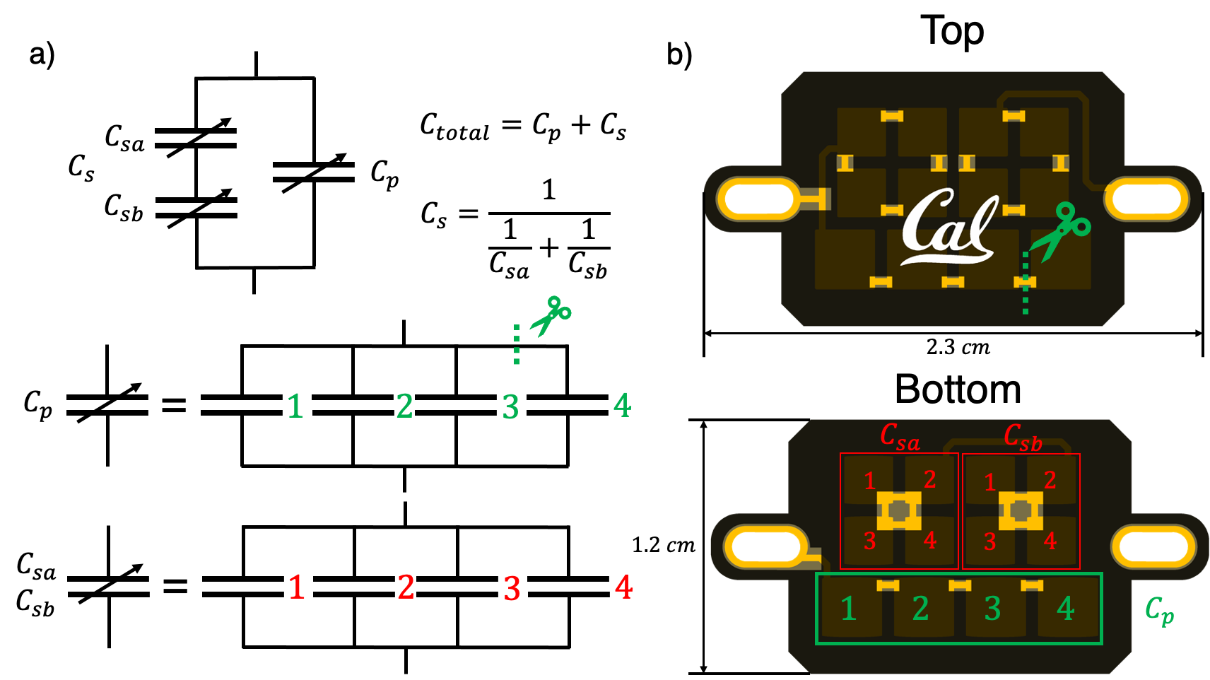
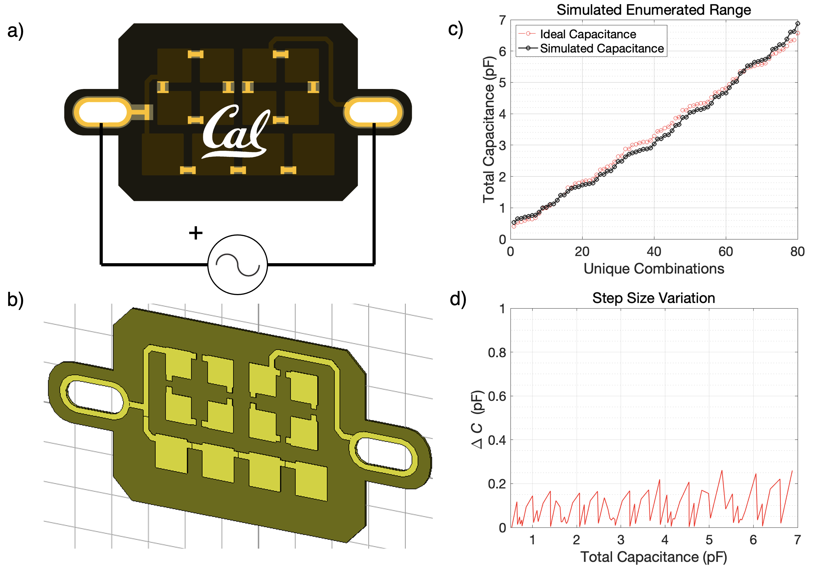
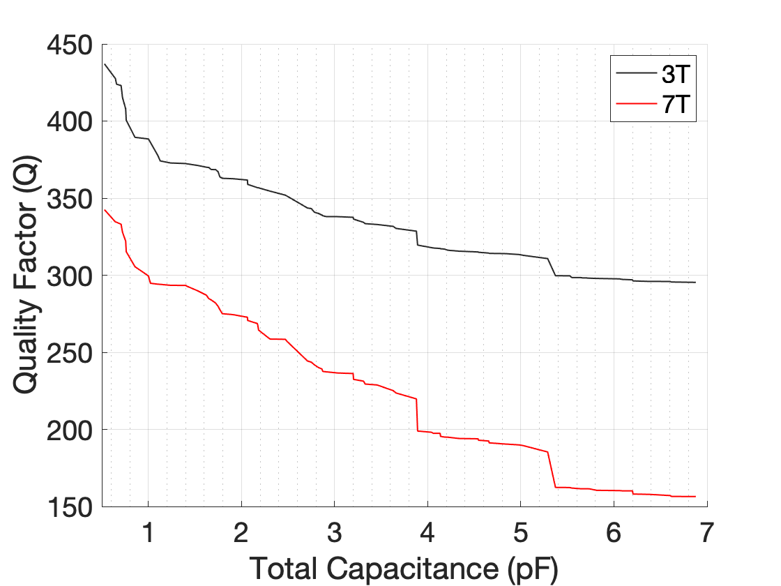
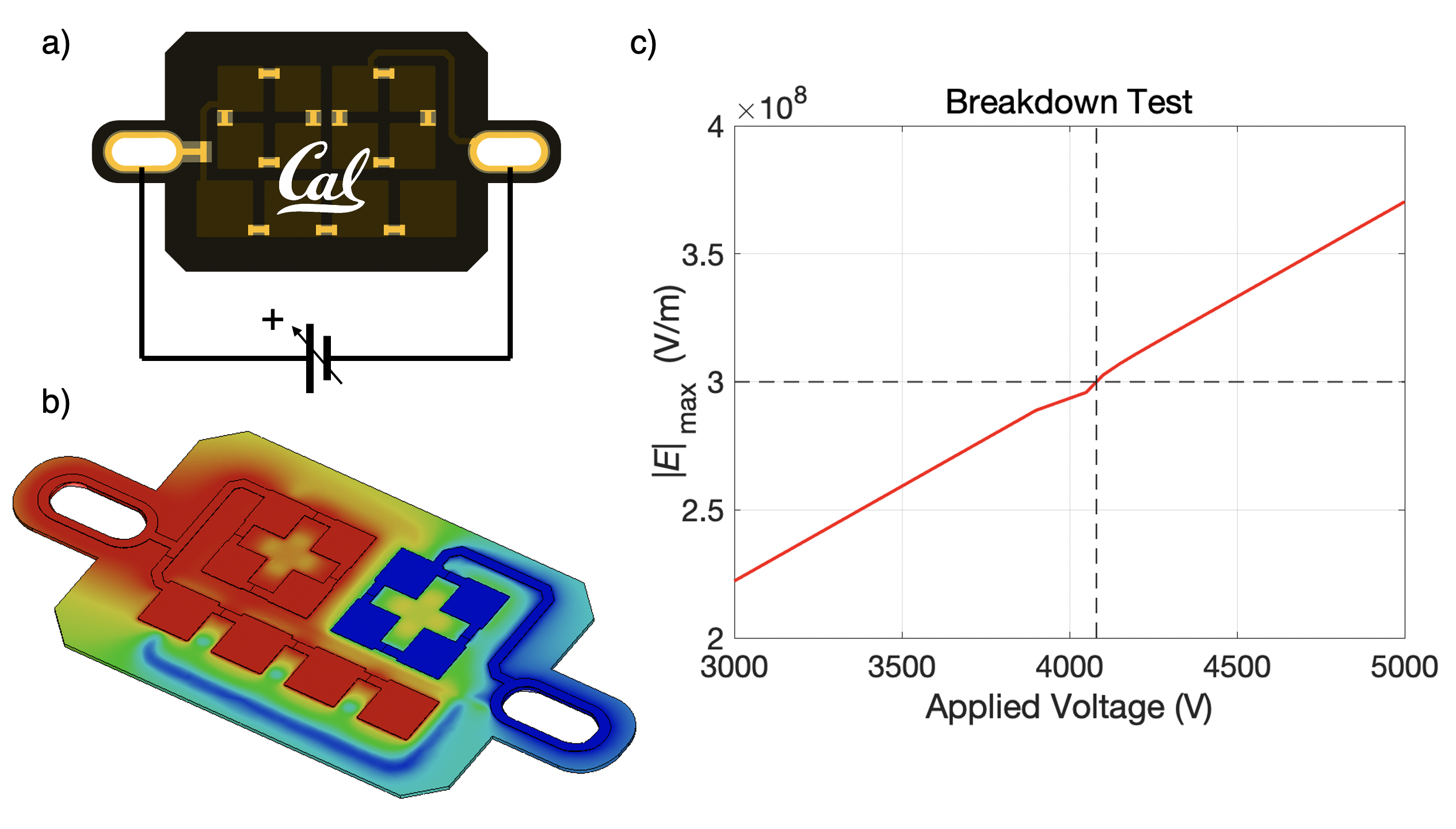
Figure 4: Breakdown Voltage Simulation, a) A voltage sweep is used to calculate the maximum electric field magnitude on the board. b) Heat map showing areas of high and low potential (red/blue). c) Maximum Electric Field Magnitude with increasing voltage, air breakdown occurs approximately at 4.1 kV while dielectric breakdown occurs at 15 kV.