1408
Galvanically Isolated RF Switches for Low Field MRI1Hyperfine Research, Guilford, CT, United States
Synopsis
RF switches occupy many roles in MRI RF systems, including spoiling, damping, transmit/receive (T/R) switches, digital tuners, and crossbar switches. For high field MRI, PIN diodes are the switching device of choice, but at low field strength FETs are attractive. However, implementing the typical drive circuitry for the switch is difficult at lower frequencies. Here we describe a novel drive circuit suitable for a broad frequency range. It does not rely on any ferrous materials, or any high frequency oscillating circuits, and is thus suitable for use on the coil.
Background
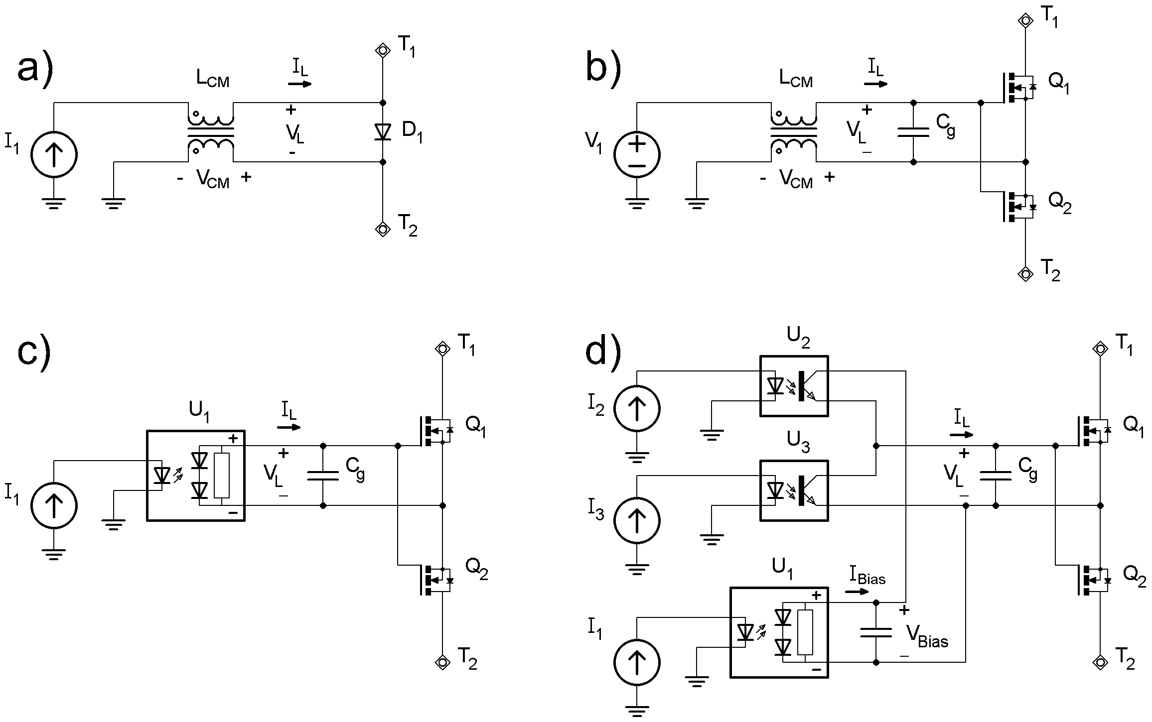
Switches in RF coils and circuits are useful building blocks for implementing detuning switches [1], T/R switches, and adjustable impedance matching networks. For high frequency, PIN diodes driven via chokes (fig 1a) are the standard solution[1]. However, the power handling of PIN diodes degrades with lower frequencies due to their finite carrier lifetimes[2]. MEMs-based switches [3]–[5] have no such low-frequency limitation, and have been proposed for use as RF switches at both low and high fields, but face issues with power handling, hot-switching reliability, ESD, and cost. FET-based switches [6] also have no low frequency limit, and are rugged with well-understood failure modes. Fig 1b shows a simple RF switch with FETs. However, a second issue arises at low frequencies: to maintain a high blocking impedance at f0, the chokes must have a much higher inductance than at high frequencies. For example, for f0=3MHz, 500µH would be appropriate, but implementing such an inductor without ferrous material is impractical. A truly isolated switch driver would be preferable.Galvanically isolated gate drivers are available off the shelf, but require isolated DCDC converters, which are implemented using high frequency switching circuits and/ferrous materials, making them unsuitable for use in MRI receivers. We have found that the RFI from such devices [7] makes them unsuitable for use near MRI coils.
Methods
Figure 1c shows a solid state relay circuit based on a photovoltaic isolator (PVI). Input current I1 drives an LED inside the PVI, which illuminates photodiodes on the other side of an isolation barrier. The photodiodes provide an open circuit voltage of 6-12V with a current of ISC=10-50µA. Well-suited for driving the gates of FETs, but not for driving PIN diodes. The rise/fall time trf is determined by the total gate charge Qg of the FETs and the short circuit current ISC of the PVI: trf= Qg/ISC.For certain switching applications (spoiling and T/R switches), the speed of this circuit is insufficient even when using small GaN FETs [8], [9]. Therefore, we developed the circuit in fig 1d. The PVI is constantly driven, and thus acts as an isolated DC power supply. The PVI output is clamped with a zener diode to limit VBIAS and VL <6V. A bypass capacitor allows peak load currents IL much higher than the ISC provided by the PVI, and thus faster switching. The driver consists of phototransistors Q1 and Q2 in a totem pole configuration. Q1 and Q2 are driven in a complementary manner with adequate dead time. Using discrete devices for the driver stage ensures that quiescent current is minimized (<1µA). The max switching frequency fSW of this circuit is determined given by fSW < ISC/Qg.
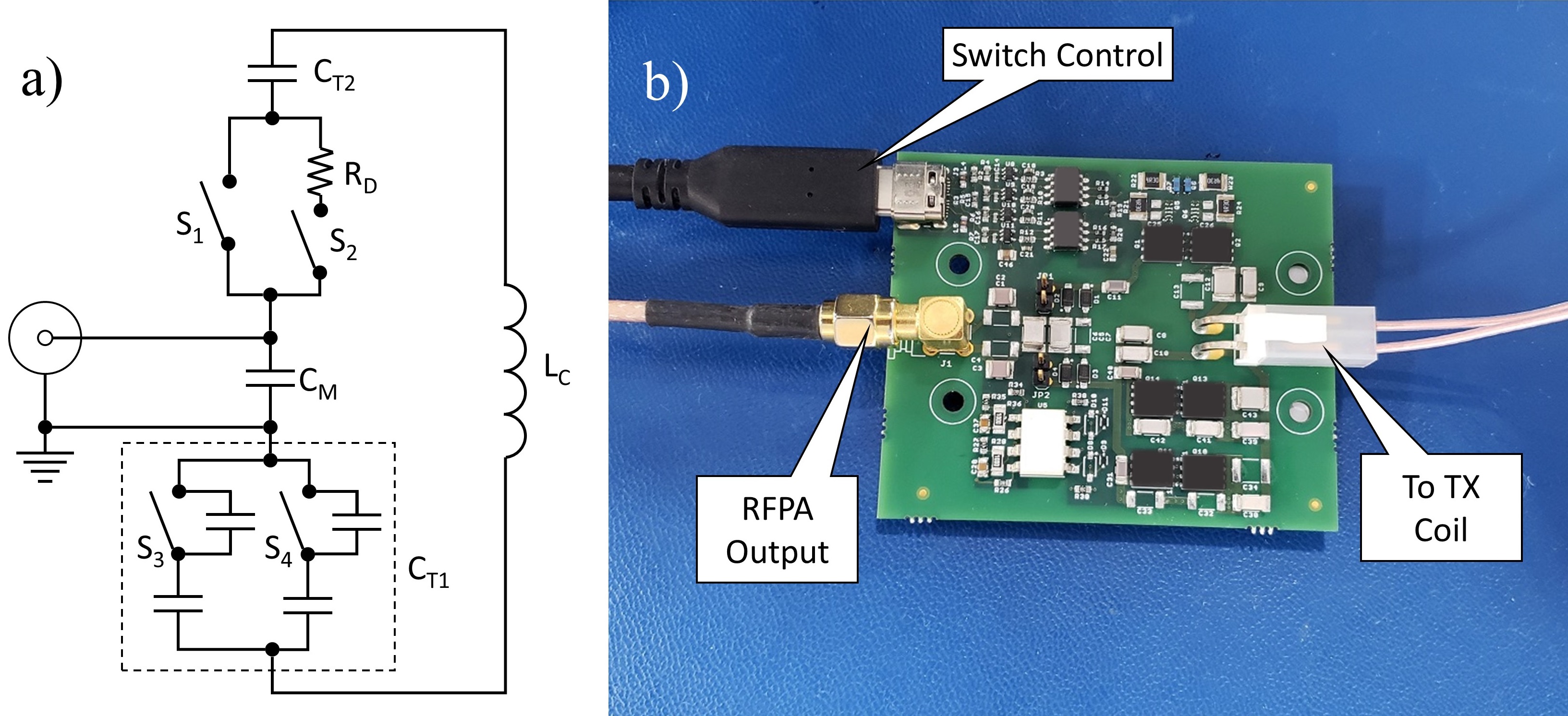
A prototype feedboard for a 2.7MHz transmit coil was developed based on these switching circuits, see fig 2. Switches S1/S2 implement spoiling and damping of the coil, respectively. S1/S2 are closed during TX pulses. When S1 is opened after the TX pulse, the coil is still tuned but damped by resistor RD. When S1 and S2 are both open, the coil is completely spoiled. S1/S2 were implemented using the fast driver circuit of fig 1d.
Switches S3/S4 together implement a tunable capacitor with two bits of resolution. This allows the center frequency of the TX coil to be adjusted to account for variations in f0 and coil inductance. These switches did not require fast switching time, and therefore were implemented with the simple SSR circuit shown in figure 1c.
Results
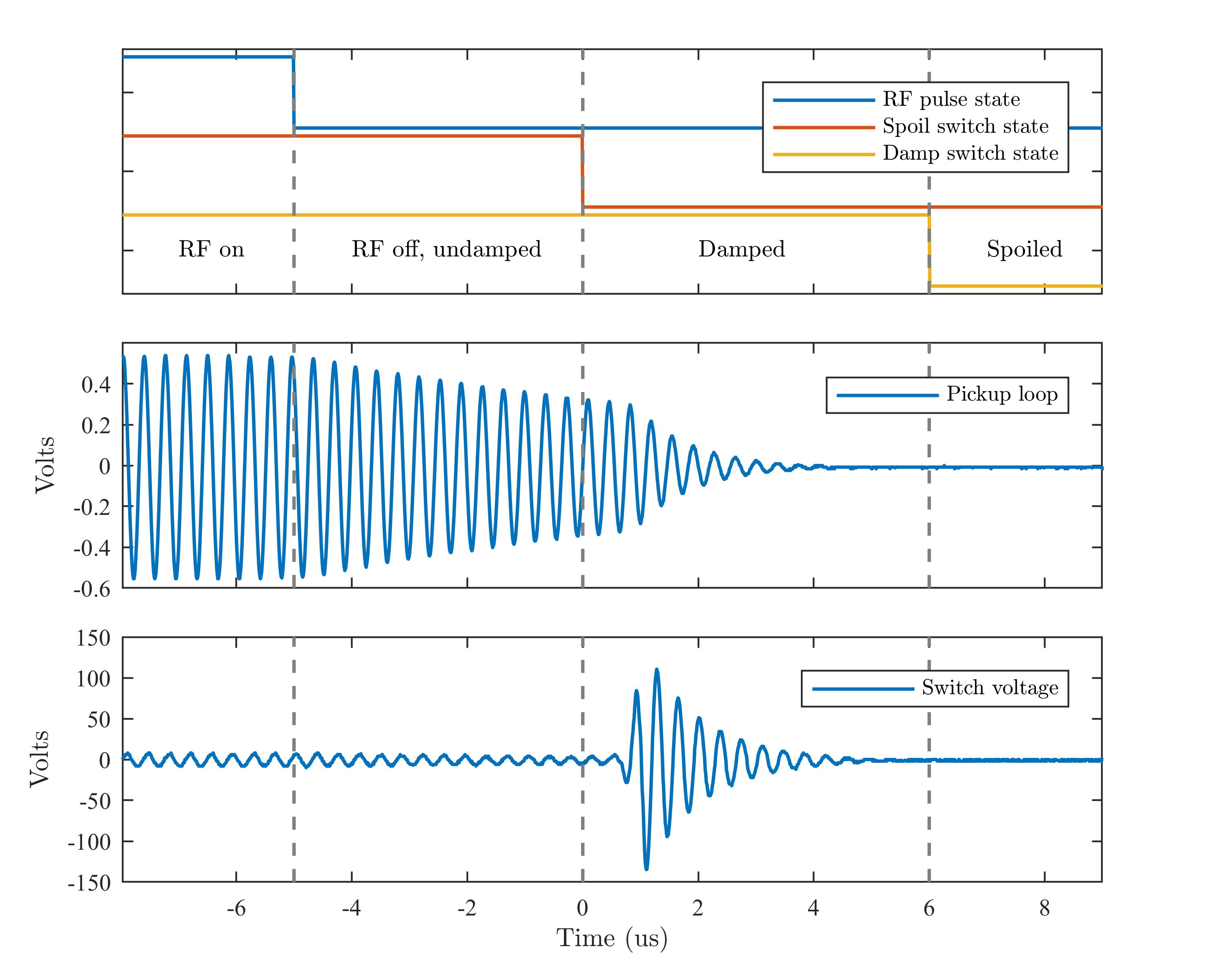
The rise and fall times of S1/S2 were 500ns, and the delay time was 900ns. An LED current of 30mA was sufficient to provide enough output current for switching frequencies up to 5kHz. Switches S1/S2 were tested by driving a 200W hard pulse into the feed board. Figure 3 shows the waveforms resulting from this experiment.At the end of the RF pulse, the coil initially rings down with a time constant t of 10.9µs. S1 turns off 5µs later, adding the damping resistance RD to the coil resistance, and the ringdown time constant decreases by a factor of 10. After another 6µs, S2 is opened to completely spoil the transmit coil.
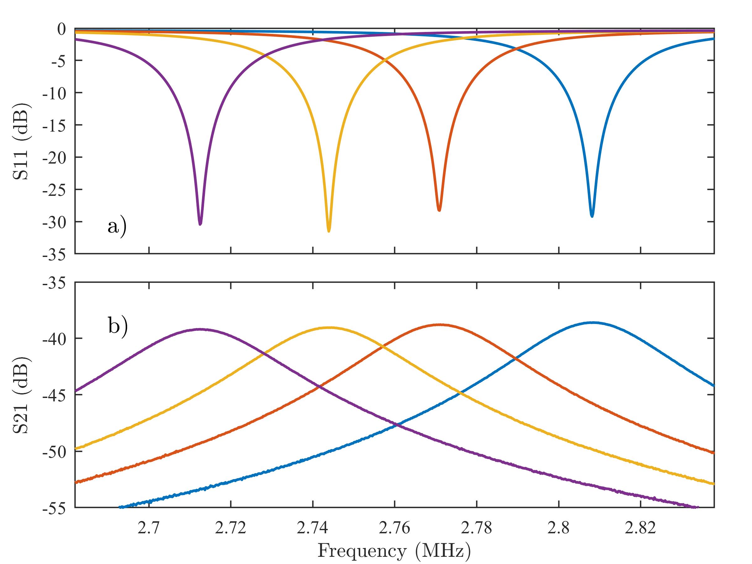
Fig 4 shows the S11 and S21 of the coil in each of the four states of S3/S4. With just two bits of tuning, the coil’s tune frequency could be adjusted over a 100kHz range. The peak B1 was found to have dropped by 10%, relative to a feedboard using only passive schottky diodes for spoiling.
Conclusion
We have demonstrated a general purpose driver for FET-based RF switches. The circuit requires no ferrous components and produces no interference, making is suitable for use in MRI receivers. The insulation of each isolator was rated to 3750Vrms or above, making it suitable for high power circuits. The total capacitance across the isolation barrier was measured to be <5pF.We have demonstrated the use of the driver for spoiling, damping, and tuning adjustment. This method should also be applicable for other purposes, such as T/R switches, crossbar switch matrices, and other tunable RF applications [10] .
Acknowledgements
No acknowledgement found.References
[1] W. A. Edelstein, C. J. Hardy, and O. M. Mueller, “Electronic decoupling of surface-coil receivers for NMR imaging and spectroscopy,” JMR, Mar. 1986.
[2] Microsemi Corp., “The PIN Diode Circuit Designer’s Handbook.” 1998, [Online]. Available: http://www.qsl.net/n9zia/pdf/pin_diode_handbook.pdf.
[3] A. Reykowski and J. Wang, “Magnetic resonance tomography apparatus and method for operating same employing an electrostatic relay,” March 2004, US6710597B2.
[4] M. Fuentes, E. Weber, S. Wilson, B. Li, and S. Crozier, “Micro-Electromechanical Systems (MEMS) based RF-switches in MRI – a performance study,” ISMRM 2010.
[5] D. Spence and M. Aimi, “Custom MEMS Switch for MR Surface Coil decoupling,” ISMRM 2015.
[6] R. HOUSEN and A. Reykowski, “Fet switch as detune circuit for mri rf coils,” Nov. 2012, WO2012160518A1.
[7] B. Chen, “iCoupler Products with isoPower Technology: Signal and Power Transfer Across Isolation Barrier Using Microtransformers.” https://www.analog.com/en/technical-articles/icoupler-products-with-isopower-technology.html.
[8] M. Twieg, M. A. de Rooij, and M. A. Griswold, “Active Detuning of MRI Receive Coils with GaN FETs,” IEEE TMTT, Dec. 2015.
[9] J. Y. Lu, K. Aggarwal, T. Grafendorfer, F. Robb, J. M. Pauly, and G. C. Scott, “Q-spoiling method using depletion mode Gallium Nitride (GaN) HEMT devices at 1.5T,” ISMRM 2015.
[10] C. Sappo, G. Gallego, X. Yan, and W. Grissom, “MEMS-based Ratio Adjustable Power Splitters for in-bore Switching of Transmit Array Compression Networks,” ISMRM 2019.
Figures