1406
Passive Tunable RF Leakage Canceller for Simultaneous Transmit and Receive (STAR) RF Coils at 1.5T Imaging1School of Biological and Health Systems Engineering, Arizona State University, Tempe, AZ, United States, 2Center for Magnetic Resonance Research, Department of Radiology, University of Minnesota, Minneapolis, MN, United States, 3Zuckerman Institute, Columbia University, New York, NY, United States
Synopsis
Simultaneous Transmit and Receive (STAR) requires high decoupling between the RF transmitter and receiver. Current methods for this include, but are not limited to: geometric isolation, active RF leakage cancellation and metamaterial decoupling. The presented method uses a passive, four-port, tunable canceller circuit to achieve upwards of 40 dB of isolation between a quadrature transmit coil pair and the single receiving coil for a 1.5T system.
Introduction
Because STAR, also denoted as CEA1 for “Concurrent Excitation and Acquisition” requires high transmitter-receiver isolation (greater than 70 dB), multiple layers of isolation are required to not overflow the dynamic range of the pre-amplifier and to extract MR signals2. Geometric coil decoupling and active RF leakage cancellation do not necessarily provide enough isolation, and metamaterials tend to be bulky for the large wavelength of 1.5T (64MHz Larmor frequency)3. Utilizing multiple layers of isolation (i.e. using geometric decoupling along with a canceller circuit) pushes us closer to STAR’s requirements. Another layer of isolation can thus come from a transmitter-receiver canceller circuit based on microstrip coupled lines with passive, tunable components when it is tuned to the target Larmor frequency.Methods
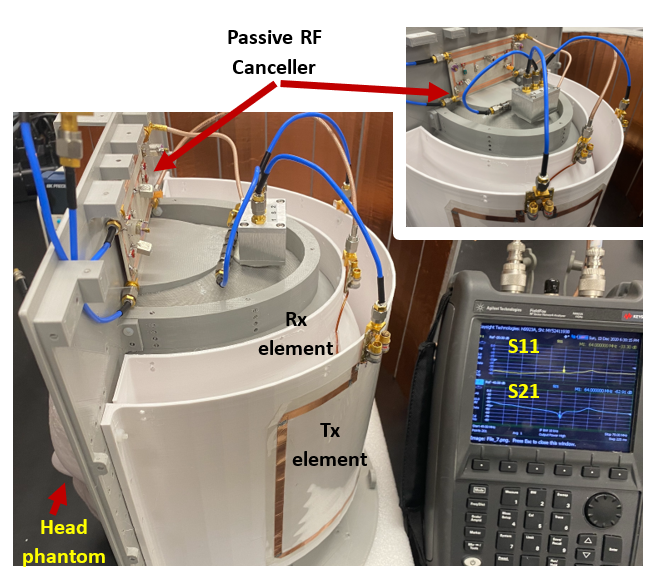
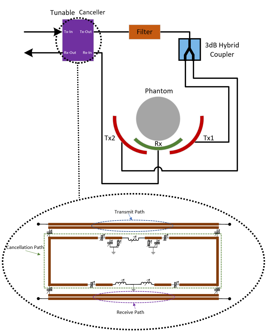
The system contains a quadrature pair of transmit RF coil elements, a single receive coil element, a hybrid coupler, a filter and the passive tunable canceller, as shown in figures 1 and 2. The canceller circuit consists of four ports: transmit-in, transmit-out, receive-in and receive-out. The schematic is also shown in figure 2, where the circuit is composed of three sections: the transmit path, the receive path and the cancellation path. Transmit-in and transmit-out are directly connected via microstrip lines, as are receive-in and receive-out. Transmit-in and receive-out are connected to the vector network analyzer to measure S21 (isolation) and S11 (Tx return loss) on the bench, while transmit-out and receive-in are connected to the RF coil elements. Both the transmit and receive microstrip lines are coupled to another pair of microstrip lines, which feed the cancellation path as a network of tunable capacitors, inductors, and resistors. A narrowband analysis of this type of network has been reported previously4 and 5. As these tunable devices are varied, the sampled RF signal from the transmit line to the receive line undergoes destructive interference through the cancellation path. This destructive interference stems from the tuning of the amplitude of a cancellation signal via resistors and the phase of the cancellation signal via capacitors and inductors. The system is tuned when decoupling is maximized while maintaining coil performance.Results and Discussion
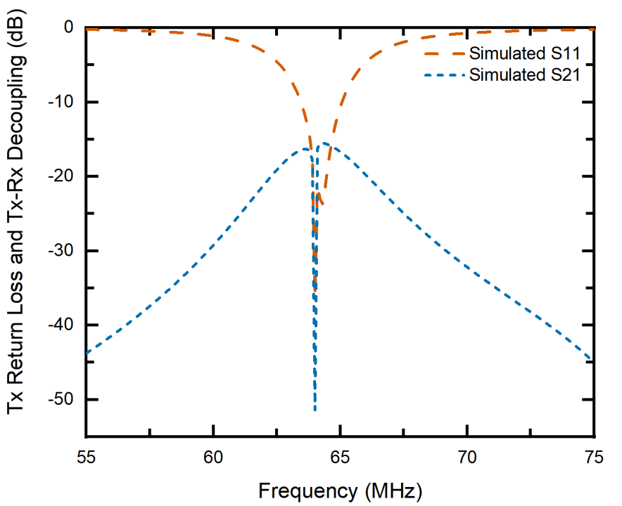
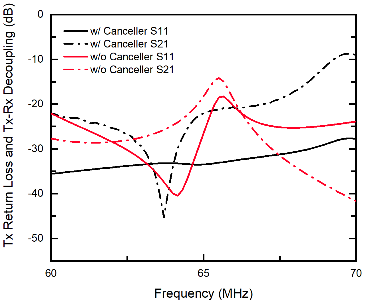
Using Keysight’s ADS, the entire system was simulated with the coils and a phantom model. Figure 3 shows the simulated results, where we can see the return loss (S11) of the transmitting antenna to be approximately 35 dB with a decoupling factor (S21) of more than 50 dB. Figure 4 shows the physical system data with and without the canceller present. With the canceller added to the system and comparing the red dot-dash line to the black dot-dash line, we get an increase in isolation from around 25 dB to 40 dB. The change in transmit coil return loss from 40 dB to 35 dB is seen by comparing the solid red line to the solid black line—a negligible difference in terms of transmit power loss. The reason for such a flat and low return-loss plot with the canceller bench test is due to the use of a quadrature setup, thus using a 3 dB hybrid coupler feed with a higher bandwidth than the coil. In practice, 40 dB of isolation can be achieved but not sustained due to coil tuning and loading sensitivity. This sensitivity issue is currently being investigated by adding an active matching circuit after the transmit-out port.Conclusion
High isolation between the transmitter and receiver is critical for STAR. A passive and tunable canceller provides a quick, simple, low cost, low power means of contributing to the isolation stack with a nominal cancellation of 40 dB and without degradation to transmitter power. The residual leakage signal after this canceller can be removed in the digital domain after the preamplifier. In addition, this decoupling technique would be useful for general purpose RF coil decoupling between channels.Acknowledgements
No acknowledgement found.References
1. A. C. Özen, E. Atalar, J. G. Korvink, and M. Bock, “In vivo MRI with Concurrent Excitation and Acquisition using Automated Active Analog Cancellation,” Sci. Rep., vol. 8, no. 1, pp. 1–12, 2018, doi: 10.1038/s41598-018-28894-w.
2. Sohn, S.‐M., Vaughan, J.T., Lagore, R.L., Garwood, M. and Idiyatullin, D. (2016), In vivo MR imaging with simultaneous RF transmission and reception. Magn. Reson. Med., 76: 1932-1938. https://doi.org/10.1002/mrm.26464
3. Duan, G., Zhao, X., Anderson, S. W., & Zhang, X. (2019). Boosting magnetic resonance imaging signal-to-noise ratio using magnetic metamaterials. Communications Physics, 2(1). https://doi.org/10.1038/s42005-019-0135-7
4. K. Nishimoto, H. Makimura, T. Yanagi, Y. Nishioka, Y. Nofumi, and H. Miyashita, “Narrowband/Wideband Decoupling Networks for Antenna Arrays and Exciation Distribution Control,” IEEE.
5. S. -M. Sohn, A. Gopinath and J. T. Vaughan, "A Compact, High Power Capable, and Tunable High Directivity Microstrip Coupler," in IEEE Transactions on Microwave Theory and Techniques, vol. 64, no. 10, pp. 3217-3223, Oct. 2016, doi: 10.1109/TMTT.2016.2602835.
Figures