1405
Lightweight metasurface pads for passive RF shimming in 3T abdominal imaging
Tania del Socorro Vergara Gomez1,2, Marc Dubois1,2,3, Pierre Jomin2, Megdouda Benamara3, Djamel Berrahou3, Elodie Georget3, Tryfon Antonakakis3, David Bendahan1, Frank Kober1, Stefan Enoch2, and Redha Abdeddaim2
1Aix Marseille Univ, CNRS, CRMBM, Marseille, France, 2Aix Marseille Univ, CNRS, Centrale Marseille, Institut Fresnel, Marseille, France, 3Multiwave Imaging, Marseille, France
1Aix Marseille Univ, CNRS, CRMBM, Marseille, France, 2Aix Marseille Univ, CNRS, Centrale Marseille, Institut Fresnel, Marseille, France, 3Multiwave Imaging, Marseille, France
Synopsis
Abdominal imaging at 3T suffers from B1+ inhomogeneities due to radiofrequency (RF) wavelength reduction. High permittivity dielectric pads have been introduced as suitable solution to this problem. Such pads can require up to a few kilograms of ceramic powder usually dispersed in water. This could be detrimental to patient comfort during examination. Here we present a new approach based on thin, lightweight and flexible metasurface pads. The pads are shown to improve transmit and receive efficiency together with SNR in vitro.
Introduction
3T MRI systems are now routinely used. Given the proton Larmor frequency i.e. 127MHz, the vacuum wavelength is more than 2 meters while the body high permittivity leads to a significant wavelength reduction, below 30 cm. On that basis, imaging large volumes such as abdomen or pelvis is problematic, and inhomogeneities of the transmit RF field have been reported1-3. High-permittivity dielectric pads have been used as an efficient solution4-8. Nevertheless, they tend to be bulky and heavy. Therefore, we developed an alternative approach based on thin and light metasurface pads. They were inspired from previously presented coupled-wire metasurface coils which were introduced as resonant devices9-11. Here, we designed passive RF shimming structures with low quality-factor hybridized resonators to prevent detuning of the main RF coils5.Materials and Methods
Pads designed in the present study worked under the hybridization mode principle12 and were tested in a 3T Vida MRI scanner (Siemens Healthineers, Erlangen, Germany). The integrated whole-body birdcage coil was used for transmission, and an 18-ch surface array coil (top) and a 32-ch spinal cord coil (below) were used for signal reception. Only 12 channels of the spinal cord coil were activated. Pads were positioned on top and bottom of the phantom (Figure 1). They were inductively coupled to both transmit and receive coils. The phantom used had a T1 of 500 ms, a relative permittivity of 77 and a conductivity of 0.35 S/m.Flip Angle (FA) maps, SNR maps and their related profiles were acquired with and without the metasurface pads. Using a preconditioning RF pulse with TFL readout sequence13, FA maps were acquired in sagittal and transversal orientations using a 249V reference voltage, TR/TE= 5000/1.8ms, FA= 8°, Sinc pulse= 90°, FOV= 250x400mm, matrix size= 80x128 and 13 contiguous slices of 15mm thickness.
GRE images were acquired to calculate SNR maps (reference voltage= 249V, TR/TE= 5/2.29ms, FA= 5°, FOV= 250x400mm, matrix size= 80x128 and 80 contiguous slices of 5mm thickness). GRE images without RF input power and with uncombined amplitude and phase were acquired for each individual channel. Noise amplitude was calculated as the standard deviation of the real component of pixel values. With this method, robust noise statistics were obtained.
Results
FA maps and profiles along distinct lines are shown in Figure 2. The most inhomogeneous regions in the reference maps (e.g. without metasurfaces) were on the anterior and posterior sides of the phantom (white arrows in Figure 2). The metasurface pads redistributed the transmit magnetic field. The sagittal profile shows +70% and +120% enhancements in the top and bottom ROIs, respectively. These enhancements were balanced by losses in other regions, farther away from the center of the phantom. In the transverse profile, a maximum loss of -40% was visible at the left border (position 190 mm).The SNR maps displayed in Figure 3 illustrate that the metasurface pads did not hampered the efficiency of the receive arrays. Even though there was a 5% noise increase when using the pads, the sagittal profile showed a maximum SNR gain of +50% on the anterior side (position -90 mm) and a maximum SNR gain of +40% on the posterior side (position 90 mm). The transversal profile illustrates that the losses were directed towards the left border (position 190 mm), away from the center, with a maximum loss of -40%.
Discussion
In vivo abdominal imaging has previously shown that the highest signal loss occurred in the anterior region and on the side of the abdomen4. Figures 2 and 3 show that signal was also lost on the posterior side of the homogeneous phantom. Using two metasurface pads (top and bottom), the transmit field of the body coil was enhanced in the ROIs that initially showed signal losses (Figure 2). While the FA in the center of the phantom was not significantly affected, a 5% SNR gain could be observed. On that basis, one can suggest that the SNR gain illustrated in Figure 3 was also attributed to an improved sensitivity of the receive arrays in the presence of the pads. Drawbacks were the reduced signal in certain regions away from the center and a slightly higher noise amplitude (+5% on average) observed equally for all channels.In addition to the field improvements, the metasurface pads offer a new option for patient comfort. In previous studies, the dielectric pads weights ranged from 2 to 4kg4,6-8. In the present study, the metasurface pad was 10 times lighter i.e. 350gr. Moreover, due to the rather large thickness of dielectric pads (1.5cm minimum for high-permittivity pads8), Rx arrays have to be positioned away from the patient. Consequently, SNR during deep organ imaging could be diminished8. Meanwhile, the metasurfaces are 1.5mm thick, including the fabric used for protection.
Conclusion
We showed that metasurface pads could locally improve both transmit and receive efficiencies. In particular, the proposed pads were shown to homogenize the field across a central sagittal slice from the anterior to the posterior side. Due to their light weight, these pads could be an efficient alternative to dielectric pads.Acknowledgements
This work has received funding from the European Union Horizon 2020 Research and Innovation program under Grant Agreement No. 736937. The project leading to this publication has received funding from Excellence Initiative of Aix-Marseille University - A*MIDEX, a French "Investissements d'Avenir" programme.References
- Schick, F. Whole-body MRI at high field: technical limits and clinical potential. European radiology. 2005;15(5):946-959.2.
- Bernstein, M A, Huston III, J, Ward, H A. Imaging artifacts at 3.0 T. Journal of Magnetic Resonance Imaging: An Official Journal of the International Society for Magnetic Resonance in Medicine. 2006;24(4):735-746.3.
- Soher, B J, Dale, B M, Merkle, E M. A review of MR physics: 3T versus 1.5 T. Magnetic resonance imaging clinics of North America. 2007;15(3):277-290.4.
- Schmitt, M, Feiweier, T, Horger, W, et al. Improved uniformity of RF-distribution in clinical whole body imaging at 3T by means of dielectric pads. In Proceedings of the Annual Meeting of ISMRM. 2004; 12:197.5.
- Schmitt, M, Feiweier, T, Voellmecke, E, et al. B1-Homogenization in abdominal imaging at 3T by means of coupling coils. In Proceedings of the Annual Meeting of ISMRM. 2005;13:331.6.
- Sreenivas, M, Lowry, M, Gibbs, P, et al. A simple solution for reducing artefacts due to conductive and dielectric effects in clinical magnetic resonance imaging at 3 T. European journal of radiology. 2007;62(1):143-146.7.
- Franklin, K M, Dale, B M, Merkle, E M. Improvement in B1‐inhomogeneity artifacts in the abdomen at 3T MR imaging using a radiofrequency cushion. Journal of Magnetic Resonance Imaging. 2008;27(6):1443-1447.8.
- Brink, W M, Webb, A G. High permittivity pads reduce specific absorption rate, improve B1 homogeneity, and increase contrast‐to‐noise ratio for functional cardiac MRI at 3 T. Magnetic resonance in medicine. 2014;71(4):1632-1640.9.
- Zubkov, M, Hurshkainen, A A, Brui, E, et al. Small‐animal, whole‐body imaging with metamaterial‐inspired RF coil. NMR in Biomedicine. 2018;31(8):e3952.10.
- Vergara Gomez, T S, Dubois, M, Glybovski, S, et al. Wireless coils based on resonant and nonresonant coupled‐wire structure for small animal multinuclear imaging. NMR in Biomedicine. 2019;32(5):e4079.11.
- Hurshkainen, A, Nikulin, A, Georget, E, et al. A novel metamaterial-inspired RF-coil for preclinical dual-nuclei MRI. Scientific reports. 2018;8(1):1-13.12.
- Jouvaud, C, Abdeddaim, R, Larrat, B, et al. Volume coil based on hybridized resonators for magnetic resonance imaging. Applied Physics Letters. 2016;108(2):023503.13.
- Chung S, Kim D, Breton E, Axel L. Rapid B1 + mapping using a preconditioning RF pulse with TurboFLASH readout. Magnetic resonance in medicine. 2010;64(2):439–446.
Figures
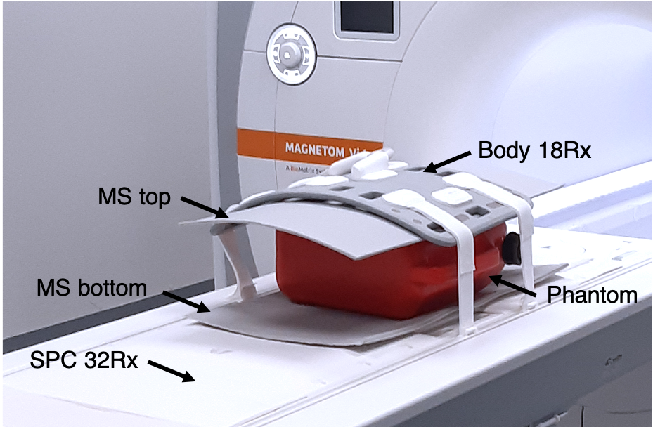
Figure 1. Experimental setup. The metasurface pads (MS) were placed between the receiver array coils and the phantom, one on top and one bellow.
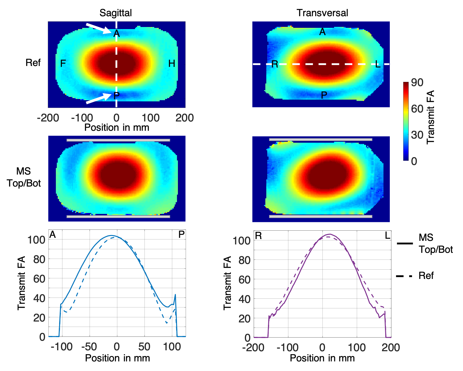
Figure 2. Flip angle maps and profiles in sagittal and transversal orientation. First row shows the reference (Ref) maps acquired without the metasurface pads (MS). Second row: maps acquired using the pads (gray rectangles). The regions of interest are indicated with white arrows. Bottom row: sagittal and transversal profiles along the dashed lines in the upper row.
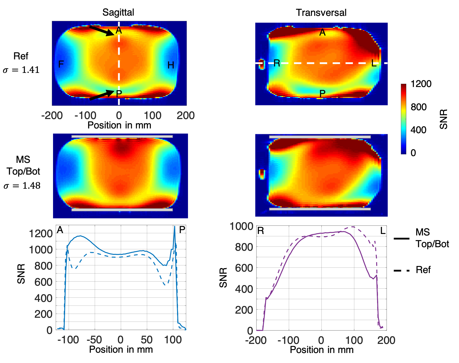
Figure 3. SNR maps and profiles in sagittal and transversal orientation. First row: reference (Ref) maps. Second row: maps acquired with the pads (MS, gray rectangles). The noise standard deviations evaluated for each experiment is shown on the left side. Regions of interest are shown with black arrows. Bottom Row: sagittal and transversal profiles along the dashed lines shown in the upper row.