1401
Correcting meander-line surface coil fields for large-area near-surface imaging1Applied Physics Division, National Institute of Standards and Technology (NIST), Boulder, CO, United States, 2NINDS, National Institutes of Health (NIH), Bethesda, MD, United States
Synopsis
Planar meander-line coils have been proposed as ideal surface coils because they should, theoretically, create highly uniform fields over planes of essentially unlimited area. Experimentally, however, field uniformity of planar meander-line coils is often worse, not better, than even simple loop surface coils. This presentation shows why existing predictions of meander-line coil fields and imaging performance are misinterpreted and how coil geometries can be simply corrected to better match theory. In particular, it is shown how a single extra turn of wire can increase field uniformity by at least an order of magnitude, allowing for uniform, large-area near-surface imaging.
Introduction
Although signal-to-noise ratios (SNR) of surface coils1 exceed those of volume coils for near-surface imaging, their B1 field uniformity seriously lags volume coils. This poor field uniformity often limits imaging and/or spectroscopy to only a small “sweet spot” some distance from the coil surface, limiting imaging area and adversely impacting ultimate achievable SNR. Meander-line2,3, or “zig-zag” or “serpentine”, coils have been proposed as a possible alternative to more common surface coils because such meander-line geometries should be able, at least theoretically, to create highly uniform fields over planes of essentially unlimited area. In reality, however, meander-line coils have yet to gain much acceptance in NMR or MRI, possibly because existing meander-line coils do not come near to achieving their promised field uniformities. This paper addresses why existing meander-line coils fall so short of their ideal theoretical behavior. In particular, we show why meander-line coils, even those consisting of many turns of wire, cannot be approximated as infinite systems, as is commonly taken for granted in the theoretical analysis of such coils. We also show how this erroneous approximation is directly responsible for increased coil field inhomogeneity and show how coil geometries can be redesigned to more closely approach their promised field uniformities.Theory
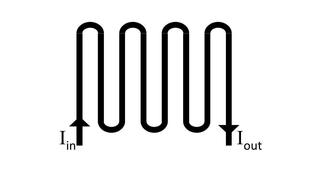
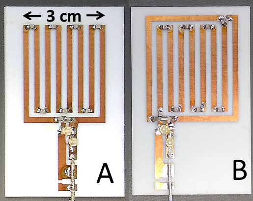
Apart from capacitance breaks, a meander-line coil consists of one continuous wire looped back and forth to create a number of connected parallel wire segments in which the current flows in alternate directions (see Fig 1). To simplify analysis, the fields of such coils are generally modeled as approximations to the field of a coil with infinitely many antiparallel wire segments. Because of the spatially alternating current direction, such infinite fields can be shown to decay exponentially away from the coil surface and, in planes parallel to the plane of coil, to become increasingly homogeneous with increasing distance from the coil. This homogeneity is a primary motivator for using such coils for large-area near-surface imaging. Unfortunately, this increasing homogeneity does not actually occur for a finite coil; instead, counterintuitively, the field homogeneity can actually worsen with increasing distance. While the impact on field uniformity of this failure of finite meander-line coils to approximate infinite coils seems not to have been appreciated in NMR / MRI circles, it has been recognized long ago in atomic physics, where such meander-line wires are used not as coils but as magnetic mirrors4,5. Here we translate the atomic physics results into terms applicable to coil design, using those insights to redesign the meander-line geometry so that it better matches theory and creates more uniform fields over large areas. A key insight is that because of the non-linear exponential decay of a meander-line coil field, the ability of the finite coil to approximate an infinite one, depends only logarithmically on the number of wires. Therefore, a finite coil quickly fails to look like an infinite coil no matter how many back and forth turns of wire it contains. We show how this difference between a finite and infinite coil is directly responsible for coil field inhomogeneity and, as indicated in figure 2 and further explained in the presentation, how the coil can be made to approximate an infinite one by adding a single correcting split-return wire around the coil’s edges. A second key insight translatable to NMR coil design is that there exists an even-odd parity effect on the number of wires in the coil, which, as seen in figures 3 and 4 and as will be explained further in the presentation, leads to the odd coil outperforming the even one.Experiment
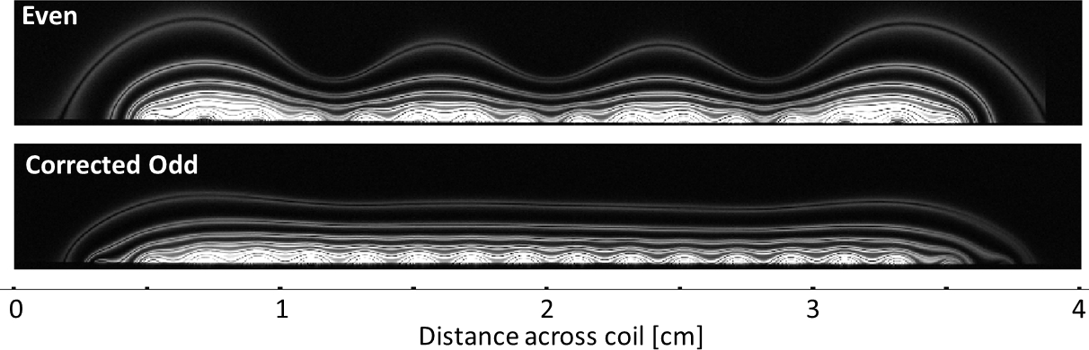
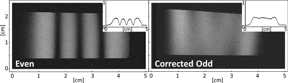
To validate the above theory, we compare two coils as shown in figure 2. The first contains an even number of wires; the second, an odd number together with a correcting split return current. Figure 3 shows side-view MRI images mapping out magnetic field contours above the coils. The coils lie along the base of the image, in a plane perpendicular to the image plane with their wires looping back and forth, in and out of the image plane. Images were generated by deliberately overpowering the RF coil to generate multiple 2π rotations in the surrounding water leading to a series of repeated maxima and minima in the image dependent on flip angles, which are proportional to the coil’s magnetic field magnitude at each location. That is, lines of maximum image intensity directly map contour lines of equal magnetic field magnitude. Each line splits into a pair of lines because maxima occur at both +/- the steady state Ernst angle about each 2π rotation. It can be seen that (i) while the field uniformity starts to improve with increasing distance from the coil, it rapidly deteriorates again for a finite coil and (ii) the corrected coil offers considerably better field uniformity. Figure 4 shows signal intensity in top-down view, in planes parallel to coil, showing again the increased uniformity of the corrected odd coil versus the uncorrected even one.Conclusion
We suggest a simple geometrical correction that improves the field uniformity of meander-line coils over an order of magnitude, making such corrected coils promising candidates for large-area near-surface imaging and spectroscopy applications.Acknowledgements
This work was supported in part by the NIH NINDS Intramural Research Program. We thank the NIH Mouse Imaging Facility for use of their MRI scannersReferences
1. J.J.H. Ackerman, T.H. Grove, G.G. Wong, D.G. Gadian, G.K. Radda, Mapping of metabolites in whole animals by P-31 NMR using surface coils, Nature 283 (1980) 167-170.
2. S.A. Bogacz, J.B. Ketterson, NMR in normal 3He with a meander-line coil, Phys. Rev. Lett. 57 (1986) 591-594
3. T. Nakada, I.L. Kwee, T. Miyazaki, N. Iriguchi, T. Maki, 31P NMR spectroscopy of the stomach by zig-zag coil, J. Magn. Reson. 5 (1987) 449-455
4. G.I. Opat, S.J. Wark, A. Cimmino, Electric and magnetic mirrors and gratings for slowly moving neutral atoms and molecules, Appl. Phys. B 54 (1992) 396-402
5. G. Zabow, M. Drndic, J.H. Thywissen, K.S. Johnson, R.M. Westervelt, M. Prentiss, Improving the specularity of magnetic mirrors for atoms, Eur. Phys. J. D 7, 351 (1999).
Figures