1400
MR imaging with a standard electro-optical modulator: Initial results
Paul Nobre1, Gwenaël Gaborit2,3, Raphaël Sablong1, Lionel Duvillaret3, and Olivier Beuf1
1Univ. Lyon, INSA-Lyon, Université Lyon 1, UJM-Saint Etienne, CNRS, Inserm, CREATIS, UMR 5220, U1206, Villeurbanne, France, 2Université de Savoie, IMEP-LAHC, UMR 5130, Le Bourget-du-Lac, France, 3KAPTEOS, Sainte-Hélène-du-Lac, France
1Univ. Lyon, INSA-Lyon, Université Lyon 1, UJM-Saint Etienne, CNRS, Inserm, CREATIS, UMR 5220, U1206, Villeurbanne, France, 2Université de Savoie, IMEP-LAHC, UMR 5130, Le Bourget-du-Lac, France, 3KAPTEOS, Sainte-Hélène-du-Lac, France
Synopsis
The large majority of receiver clinical MR coil are using cables between the resonant coil and Connector plug. To remove possible induced currents on the cable’s shield, circuits such as RF traps are distributed along the cable. This is done to ensure patients’ safety during the exam. RF-traps are difficult to miniaturize and are not fit for inner coils such as endoluminal coils. Optical fibers would be a smart option to get rid of this critical drawback but this requires electro-optical conversion devices. This abstract presents the first images obtained at 7T with an electro-optical conversion based on Pockel’s effect.
Introduction
To ensure patients’ safety, several norms exist to govern MRI exams, some of which set the maximal SAR1 (To avoid any increase superior to 1C° of temperature). Nevertheless, it can be challenging to estimate properly the local SAR. In addition to time-varying gradients and radiofrequency impulsions B1, the galvanic link between the coil and the MRI console is a matter of concern. Common mode currents can appear in the outer conductor of the coaxial cable while being exposed to RF excitation of NMR sequences. Resulting standing waves along the cable show some electrical field concentration zones and currents can be induced in the patient’s tissues, potentially provoking burns2. Circuits such as cable traps3 are commonly used to minimize that effect, but at the cost of cable inflexibility, increased cable diameter and additional weight, which can be problematic in certain conditions (arrays of surface coils, endoluminal coils). It is also worth noting that this problem increases along with the static magnetic field. An optical link on the other hand would address all these issues. In this work, an EO modulation of NMR signal making use of Pockel’s effect was used and transmitted by optical fibers before being electrically converted to be processed by NMR system.Methods
All acquisitions were performed on a 7T preclinical MRI scanner (Bruker, Germany) at the proton frequency of 300.13MHz. A quadrature 23mm inner diameter volume coil was used (RapidBiomed, Germany). The coil was interfaced with a quadrature hybrid coupler giving access separately to transmit and receive signals. The receive port is connected to the RF port of the electro optic (EO) commercial modulator, a LN82S-FC (Thorlabs, Germany) 15GHz band intensity modulator. As the electrical field varies through the modulator’s lithium niobate crystal, it changes its refractive index. Half of the light emitted by the laser goes through the crystal and the change of refractive index induces a change of phase. The light recombines, (constructively or destructively), effectively modulating the light intensity according to the electrical receiver NMR signal. Input and output optical ports of the modulator are connected to an EoSense (Kapteos, France). This apparatus includes the laser source, the detection circuit (photodiode, amplifier, etc.) converting the signal back into electric signal. The EoSense output is connected to preamplifier (HPPR module) of the MRI console. The Figure 1 summarizes the whole setup of conversion. The Phantom imaged consists in a 15mm diameter tube filled with a solution of 5g/l NaCl and 1.25g/l NiSo4. Acquisitions are alternatively performed with galvanic cable (path A) and with the optical conversion bench (path B) for comparison. A spectrum analyzer (Keysight, USA) is used to monitor the signal for both configurations (out of the coil and out of the OE conversion). This monitoring is also performed without phase encoding gradient. The sequence used is a 2D gradient Echo with an echo time of 2.5ms, a repetition time of 30ms and a flip angle of 30°.Results
Representatives images acquired with both paths are shown in figure 2. The principle of the optical conversion is effective and the MRI console was able to reconstruct an image of the phantom. The SNR however was significantly deteriorated by the optical conversion, to a thirty factor. The signal measured on the spectrum analyzer (Figure 3) without phase encoding gradient shows that with a narrow resolution bandwidth (100 KHz), the dynamic range of the signal with the noise floor level measured for both paths are the same. This fact indicates that instead of reducing the amplitude of the signal, there is a significant additional source of noise in the conversion.Discussion
There are many means of improvement, the most important being the modulator. Like most EO devices, it was developed for telecommunications networks. The large bandwidth (several GHz) needed for those applications is counterproductive here, as the product bandwidth-sensibility is a constant for a given topology4. We are working with research partners to build a modulator with a 500MHz bandwidth. A study of the behaviour of the laser and photodiode according to optical power should give more information on eventual others sources of noise. Secondly the amplifier of the photodiode is wideband, which adds noise on frequencies unused in our sequence (50KHz of useful bandwidth in this case). Developing a bandpass filter with narrower bandwidth than the MRI’s (5MHz) would cancel part of that noise.Conclusion
The principle of the NMR Electro optical conversion using Pockel’s effect is currently working at 7T, but the SNR needs to be preserved to remain suitable and attractive. Improvements at several stages of the EO conversion, along with real time electrical field monitoring5 have to be further performed.Acknowledgements
This work was funded by the AURA region and performed within the scope of LABEX PRIMES (ANR-11-LABX-0063). Experiments were performed on the PILoT facility, part of the France Life Imaging infrastructure (ANR-11-INBS-0006).References
1. IEC 60601-2-33 (https://webstore.iec.ch/publication/22705) 2. Dempsey, Mary F., Barrie Condon, et Donald M. Hadley. « Investigation of the Factors Responsible for Burns during MRI ». Journal of Magnetic Resonance Imaging 13, nᵒ 4 (1 avril 2001): 627‑31. https://doi.org/10.1002/jmri.1088. 3. Peterson & al« Common Mode Signal Rejection Methods for MRI: Reduction of Cable Shield Currents for High Static Magnetic Field Systems ». Concepts in Magnetic Resonance Part B: Magnetic Resonance Engineering 19B, nᵒ 1 (1 janvier 2003): 1‑8. https://doi.org/10.1002/cmr.b.10090. 4. R. C. Williamson, "Sensitivity–bandwidth product for electro-optic modulators," Opt. Lett. 26, 1362-1363 (2001) 5. I. Saniour et al. (2017). Electro-optic probe for real time assessments of RF electric field produced in an MRI scanner: Feasibility tests at 3 and 4.7 Tesla. NMR in Biomedicine. Vol 31. No 1.Figures
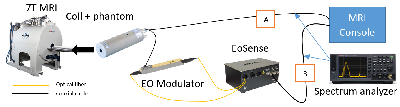
Signal conversion setup. The signal is
transmitted by coaxial cable in path A, and by coaxial cable with an EO
conversion and an OE conversion in path B. The amplitude of each signal is monitored
by a spectrum analyzer.
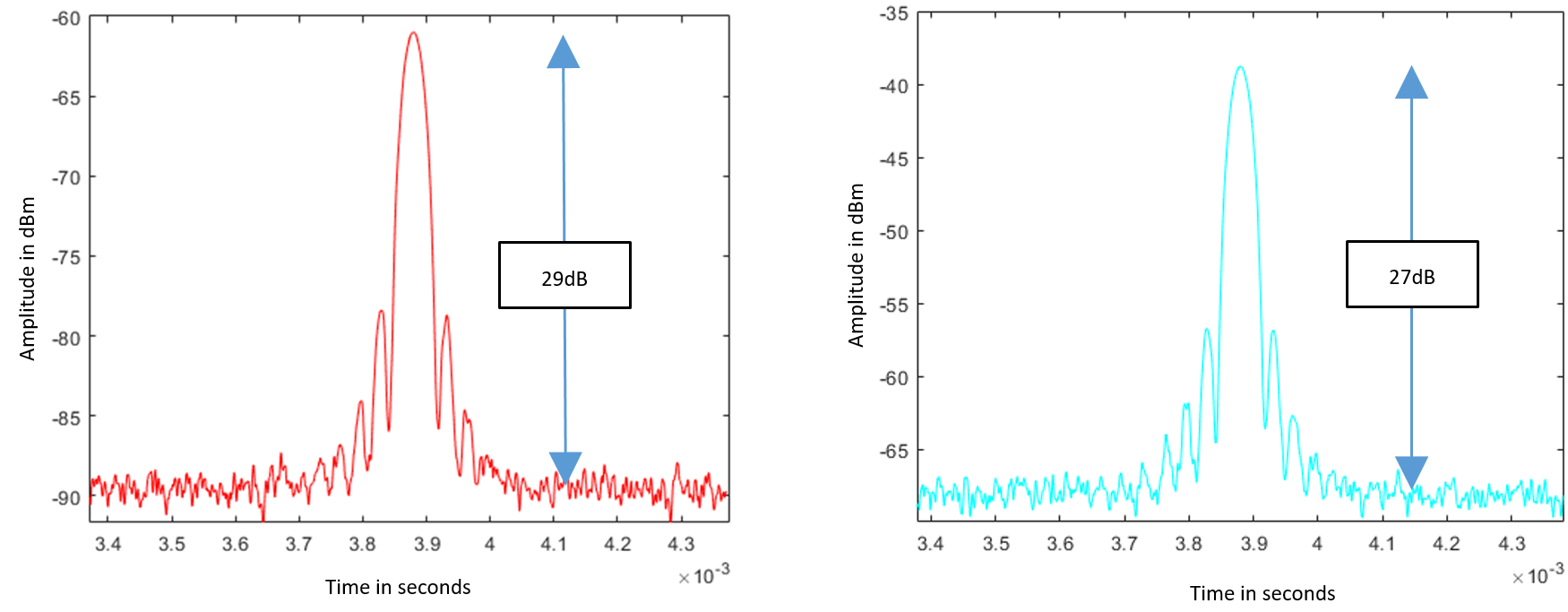
Amplitude of measured NMR signal for the
galvanic connexions (left) and galvanic with EO conversion. The noise floor
level is respectively at -90dB and -67dB without and with the EO conversion,
but the dynamic signal/noise floor level variation is negligible.
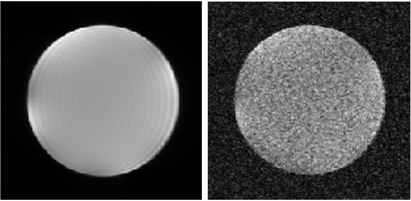
Images acquired using regular galvanic connexion
(left) and OE conversions with fiber optic transmission. The SNR are
respectively 162 and 5 (ratio of 32). Inner diameter of tube is 15mm.