1398
Non-Uniform Dielectric Substrate (NODES) Antenna Design for Cardiac Imaging at 7T
Alireza Sadeghi-Tarakameh1, Bahram Khalichi2, Xiaoping Wu1, Gregory J. Metzger1, and Yigitcan Eryaman3
1Center for Magnetic Resonance Research (CMRR), University of Minnesota, Minneapolis, MN, United States, 2Department of Electrical and Electronics Engineering, Bilkent University, Ankara, Turkey, 3University of Minnesota, Minneapolis, MN, United States
1Center for Magnetic Resonance Research (CMRR), University of Minnesota, Minneapolis, MN, United States, 2Department of Electrical and Electronics Engineering, Bilkent University, Ankara, Turkey, 3University of Minnesota, Minneapolis, MN, United States
Synopsis
Utilizing receive and transmit array coils with improved SNR/SAR performance is crucial to realizing the full potential of ultra-high field (UHF) MRI. In this work, we optimize a previously introduced antenna (NODES) to improve its SNR and SAR performances for 7T cardiac MRI applications.
Introduction
Parallel imaging and transmit array technologies are essential to taking full advantage of UHF-MRI.1-3 Previous studies4,5 demonstrated how increasing the number of transmit/receive elements in an array can improve excitation homogeneity, SAR efficiency as well as unaccelerated and accelerated SNR. This effort requires reducing the element size, which needs to be done while considering the impact on element performance.Recently, various elements, such as fractionated dipoles,6,7 combined loop-dipoles,8 snake antennas,9 bumped dipoles/loops10,11 and bowtie antennas12 were proposed for UHF MRI. Also, it has been demonstrated that placing a non-uniform dielectric substrate (NODES) underneath a short antenna can effectively impact its transmission and reception performance.13 Here, we optimize transmit (Tx) and receive (Rx) NODES antenna elements (namely NODESTx and NODESRx) to maximize SAR efficiency and SNR for 7T cardiac imaging. For a proof of concept, we modeled 16-channel Tx/Rx arrays using the NODESRx. We then compared its transmit and receive performances to the 16-channel loop-dipole (LD) Tx/Rx array8 through EM simulations.
Theory and Method
The NODES antenna were optimized by considering six design parameters (i.e., length of the conductor (l), width of the conductor at two end-points (w), the separation between the conductor and the sample (h), dielectric constants of the segmented substrate (εr1, εr2, εr3)) as we previously described.13 We set two different optimization goals resulting in two separate elements designs: one to maximize the B1+-SAR efficiency (B1+/pSAR0.5) and the other intrinsic SNR (ISNR) both at depths of 50 to 80mm from the surface of the body.$$\begin{array}{*{20}{c}}{goal\#1:}&{\mathop{\max}\limits_{l,w,h,{\varepsilon_{r1}},{\varepsilon_{r2}},{\varepsilon_{r3}}}}&{Mean\left\{{\xi(r;l,w,h,{\varepsilon_{r1}},{\varepsilon_{r2}},{\varepsilon_{r3}})~at~depth~of~50~to~80mm}\right\}}\end{array}$$
where $$$\xi(r)$$$ represents the B1+-SAR efficiency at the position r and is defined as
$$\xi(r)=\frac{{B_1^+(r)}}{{\sqrt{pSA{R_{10g}}}}}$$
where pSAR10g is the peak local 10g-averaged SAR.
$$\begin{array}{*{20}{c}}{goal\#2:}&{\mathop{\max}\limits_{l,w,h,{\varepsilon_{r1}},{\varepsilon_{r2}},{\varepsilon_{r3}}}}&{Mean\left\{{\psi(r;l,w,h,{\varepsilon_{r1}},{\varepsilon_{r2}},{\varepsilon_{r3}})~at~depth~of~50~to~80mm}\right\}}\end{array}$$
where $$$\psi(r)$$$ represents the ISNR at the position r, and is determined by B1− (right-hand circularly polarized component of the RF magnetic field) and R (the real part of the input impedance seen from the ports of the coil)14
$$\psi(r)\sim\frac{{B_1^-(r)}}{{\sqrt R}}$$
An EM simulator (HFSS) was used to simulate coil elements. We performed an exhaustive search over the results obtained from fast, coarsely meshed EM simulations. As a result, we designed NODESTx and NODESRx antennas (Fig.1). To evaluate their transmit and receive performances, we compared them to a fractionated dipole6 and loop coil8 shown in Fig.1.
To investigate the performance of these new designs for cardiac imaging at 7T, we composed a 2D 16-channel Tx/Rx array coil using theNODESRx’s (Fig.2). We compared its SAR and SNR performances to the 1D 16-channel loop-dipole Tx/Rx array coil developed for general torso imaging8 (Fig. 2a) through the EM simulations (CST) in the presence of a realistic human model (Duke) with a voxel size of 2x2x2mm3. Employing the field solutions from the three arrays (Fig.2), we performed 3D phase-only shimming to achieve maximum excitation homogeneity for an average B1+ of 1µT over the heart. Then the coefficient of variation (CoV) of the resulting B1+ distribution and pSAR10g were calculated. To compare the SNR performance of the three structures, we used sum-of-square of B1− fields generated by each individual channel for 1W of accepted power.7
Results
Fig. 3 shows the comparison between the dipole, loop, NODESTx, and NODESRx in terms of the B1+-SAR efficiency and ISNR in a uniform phantom.Fig. 4 shows the B1+-maps over the heart as obtained with two arrays. The NODESRx array shows a 40% reduction in pSAR10g compared to the LD array while preserving the same homogeneity and average B1+ value.
Fig. 5 shows the relative SNR maps over the cardiac. Array of NODESRx promises a 15% and 11% improvement in average SNR and peak SNR value, respectively, compared to the array of LD.
Discussion
In this work, the NODES antenna is optimized for cardiac imaging at 7T. Two new designs optimized separately for SAR and SNR performances can be used to construct NODESTx and NODESRx elements. Both designs required a high-permittivity block added underneath the feed point. High dielectric material blocks have been utilized in the literature to increase imaging performance.15,16 NODES optimization extends this approach to its full capacity by allowing spatial variation of dielectric material properties along the length of the conductor.Although separate designs for transmit and receive purposes are proposed, the practical eases of using a Tx/Rx array coil instead of the dedicated separate coils encourage us to choose a proper NODES antenna for both reception and transmission. Accordingly, results show that the NODESRx provides improvements in both SNR and SAR performances. Furthermore, the reasonably short size of the NODESRx enables us to assemble a whole-torso Tx/Rx array coil, which would be useful in many applications such as spine imaging.17 Despite the promising results achieved using the numerical simulations, experimental validations are essential to verifying the capabilities of the proposed design.
Conclusion
In this study, we optimized the previously proposed NODES antenna for cardiac imaging at 7T. We demonstrated the SAR and SNR improvements by comparing a 2D 16-channel Tx/Rx arrays of NODES with a 1D loop-dipole array, numerically.Acknowledgements
This work was supported by the following grants: NIBIB P41 EB027061References
- Roemer PB, Edelstein WA, Hayes CE, Souza SP, Mueller OM. The NMR phased array. Magnetic resonance in medicine. 1990 Nov;16(2):192-225.
- Adriany G, Van de Moortele PF, Wiesinger F, Moeller S, Strupp JP, Andersen P, Snyder C, Zhang X, Chen W, Pruessmann KP, Boesiger P. Transmit and receive transmission line arrays for 7 Tesla parallel imaging. Magnetic Resonance in Medicine: An Official Journal of the International Society for Magnetic Resonance in Medicine. 2005 Feb;53(2):434-45.
- Metzger GJ, Snyder C, Akgun C, Vaughan T, Ugurbil K, Van de Moortele PF. Local B1+ shimming for prostate imaging with transceiver arrays at 7T based on subject‐dependent transmit phase measurements. Magnetic Resonance in Medicine: An Official Journal of the International Society for Magnetic Resonance in Medicine. 2008 Feb;59(2):396-409.
- Lattanzi R, Wiggins GC, Zhang B, Duan Q, Brown R, Sodickson DK. Approaching ultimate intrinsic signal‐to‐noise ratio with loop and dipole antennas. Magnetic resonance in medicine. 2018 Mar;79(3):1789-803.
- Zhu Y. Parallel excitation with an array of transmit coils. Magnetic Resonance in Medicine: An Official Journal of the International Society for Magnetic Resonance in Medicine. 2004 Apr;51(4):775-84.
- Raaijmakers AJ, Italiaander M, Voogt IJ, Luijten PR, Hoogduin JM, Klomp DW, van Den Berg CA. The fractionated dipole antenna: A new antenna for body imaging at 7 T esla. Magnetic resonance in medicine. 2016 Mar;75(3):1366-74.
- Ertürk MA, Wu X, Eryaman Y, Van de Moortele PF, Auerbach EJ, Lagore RL, DelaBarre L, Vaughan JT, Uğurbil K, Adriany G, Metzger GJ. Toward imaging the body at 10.5 tesla. Magnetic resonance in medicine. 2017 Jan;77(1):434-43.
- Ertürk MA, Raaijmakers AJ, Adriany G, Uğurbil K, Metzger GJ. A 16‐channel combined loop‐dipole transceiver array for 7 T esla body MRI. Magnetic resonance in medicine. 2017 Feb;77(2):884-94.
- Steensma B, van de Moortele PF, Ertürk A, Grant A, Adriany G, Luijten P, Klomp D, van den Berg N, Metzger G, Raaijmakers A. Introduction of the snake antenna array: Geometry optimization of a sinusoidal dipole antenna for 10.5 T body imaging with lower peak SAR. Magnetic Resonance in Medicine. 2020 May 5.
- Sadeghi‐Tarakameh A, Adriany G, Metzger GJ, Lagore RL, Jungst S, DelaBarre L, Van de Moortele PF, Ugurbil K, Atalar E, Eryaman Y. Improving radiofrequency power and specific absorption rate management with bumped transmit elements in ultra‐high field MRI. Magnetic resonance in medicine. 2020 Dec;84(6):3485-93.
- Sadeghi‐Tarakameh A, DelaBarre L, Lagore RL, Torrado‐Carvajal A, Wu X, Grant A, Adriany G, Metzger GJ, Van de Moortele PF, Ugurbil K, Atalar E. In vivo human head MRI at 10.5 T: A radiofrequency safety study and preliminary imaging results. Magnetic resonance in medicine. 2020 Jul;84(1):484-96.
- Oezerdem C, Winter L, Graessl A, Paul K, Els A, Weinberger O, Rieger J, Kuehne A, Dieringer M, Hezel F, Voit D. 16‐channel bow tie antenna transceiver array for cardiac MR at 7.0 tesla. Magnetic resonance in medicine. 2016 Jun;75(6):2553-65.
- Sadeghi-Tarakameh A, Jungst S, Wu X, Lanagan M, Adriany G, Metzger GJ, Van de Moortele PF, Ugurbil K, Atalar E, Eryaman Y. A new coil element for highly‐dense transmit arrays: An introduction to non‐uniform dielectric substrate (NODES) antenna. InProceedings of the 27th Annual Meeting of ISMRM, Montreal, Canada 2019 (Vol. 732).
- Ocali O, Atalar E. Ultimate intrinsic signal‐to‐noise ratio in MRI. Magnetic resonance in medicine. 1998 Mar;39(3):462-73.
- Yang QX, Wang J, Wang J, Collins CM, Wang C, Smith MB. Reducing SAR and enhancing cerebral signal‐to‐noise ratio with high permittivity padding at 3 T. Magnetic resonance in medicine. 2011 Feb;65(2):358-62.
- Teeuwisse WM, Brink WM, Webb AG. Quantitative assessment of the effects of high‐permittivity pads in 7 Tesla MRI of the brain. Magnetic resonance in medicine. 2012 May;67(5):1285-93.
- Sadeghi-Tarakameh A, Jungst S, Wu X, Lanagan M, Adriany G, Metzger GJ, Van de Moortele P, Ugurbil K, Atalar E, Nelson F, Eryaman Y. Imaging The Spine At 10.5 T. In Multiple sclerosis journal. 2020 May; 26(1):154-155.
Figures
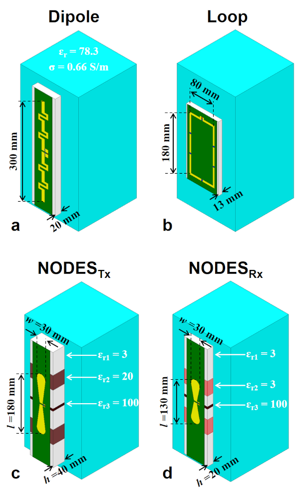
Figure 1. The EM simulation models of the (a) fractionated
dipole, (b) loop, (c) NODES antenna optimized for SAR efficiency, and (d) NODES
antenna optimized for SNR. A rectangular 200x200x400mm2 uniform
phantom with εr=78.3 and σ=0.66 S/m was used to mimic the human body electrical
properties.
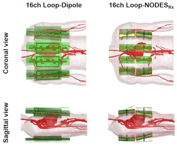
Figure 2.Coronal
and sagittal views from the formation of 16-channel 1D loop-dipole and 2D NODESRx
over the anterior and posterior sides of a realistic human body model in the EM
simulation environment. These EM simulations were used for evaluation of the
transmit and receive performances of the two arrays in cardiac imaging at 7T.
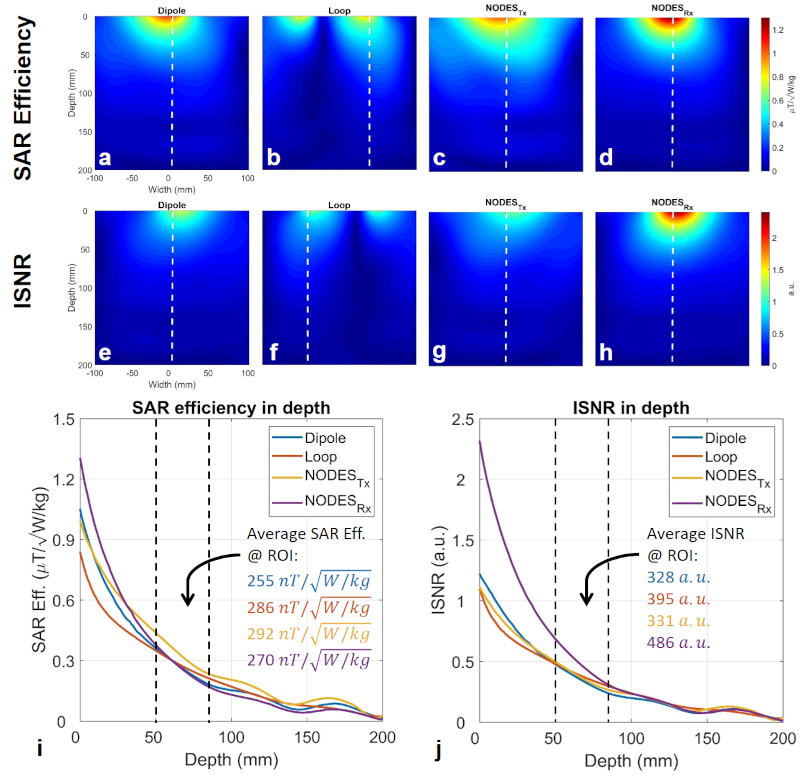
Figure 3. Comparison of Transmit and receive performances of
the single elements shown in Fig. 1. SAR efficiency maps on an axial plane
passing through the middle of the (a) fractionated dipole, (b) loop, (c) NODESTx,
and (d) NODESRx. Relative ISNR maps on an axial plane passing
through the middle of the (e) fractionated dipole, (f) loop, (g) NODESTx,
and (h) NODESRx. (i) The SAR efficiency of the single elements over
the dashed line shown in Fig. 3a-d. (j) The relative ISNR of the single elements
over the dashed line shown in Fig. 3e-h.
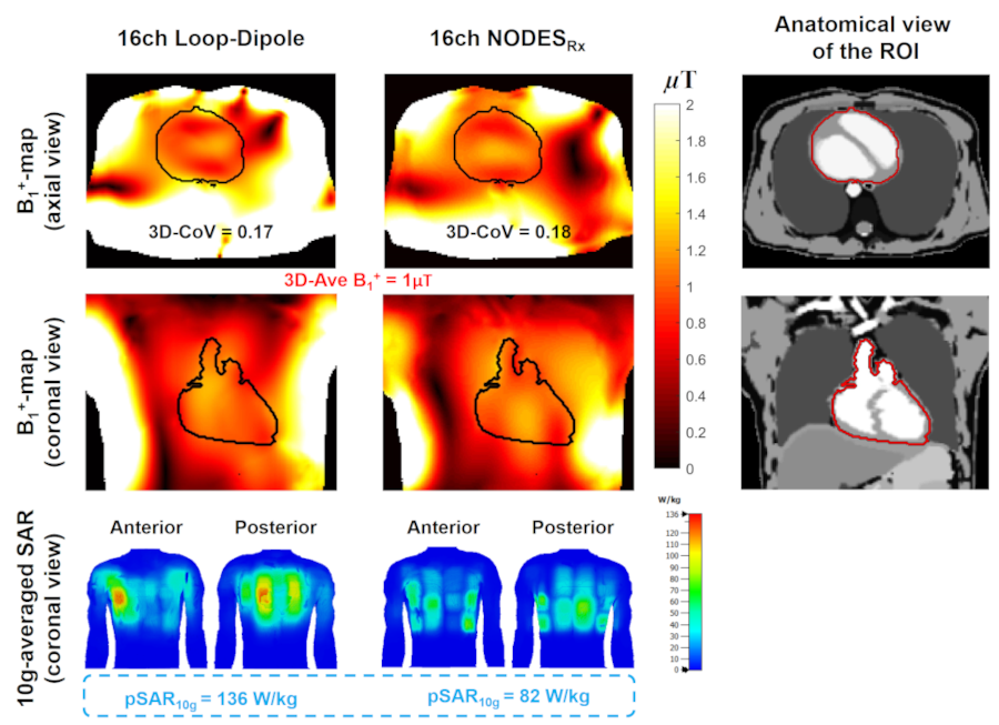
Figure 4. Transmit performance of the two arrays. First
row: An axial view of B1+-maps obtained by 3D
phase-only shimming over the heart with maximum homogeneity constraint. Second
row: A coronal view of the B1+-maps obtained by the
same shimming solution. Third row: Anterior and posterior views of the
10g-averaged SAR caused by the same shimming solution. The input power level was
adjusted to achieve the average 1µT B1+ over the heart.
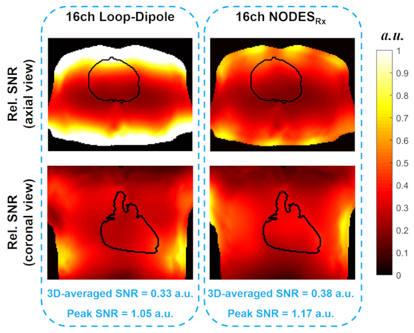
Figure 5. SNR comparison between the two arrays.