1397
Introducing the Double-Folded Dipole to enhance the Excitation Efficiency at 7T Ultra-High Field MRI1Institute of Medical Physics and Radiation Protection, TH Mittelhessen University of Applied Sciences, Gießen, Germany
Synopsis
We demonstrated a highly efficient B1+to-SAR dipole antenna for ultrahigh-field MRI which consists of a double-folded ladder structure. The antenna was simulated and bench tested. The antenna has a high impedance which provides low mutual coupling between other antenna elements. Ultimately, this characteristic possibly allows to construct antenna array for pTx.
Introduction
The need of parallel transmit arrays in ultra-high field (UHF) MRI has recently sparked a great deal of interest in using electrical dipole antennas. The underpinning current pattern of dipole antennas is considered more favorable than loop coils for approaching the ultimate signal-to-noise ratio at UHF1. Thus, radiative dipole antennas are advantageous in B1+ efficiency in the far-field region, however, they also produce higher absolute SAR values than loop coils of the same size. To address this problem, several approaches have been pursued to improve excitation efficiency (B1+/√SAR10g max) by geometrically modifying the radiative dipole antennas2-5.To further improve the B1+ to SAR efficiency, we developed a double-folded dipole (DFD) antenna for 7T MRI. The new antenna was simulated and compared with a regular dipole antenna and a fractionated dipole. A pair of DFD antennas was constructed for bench validations.
Methods
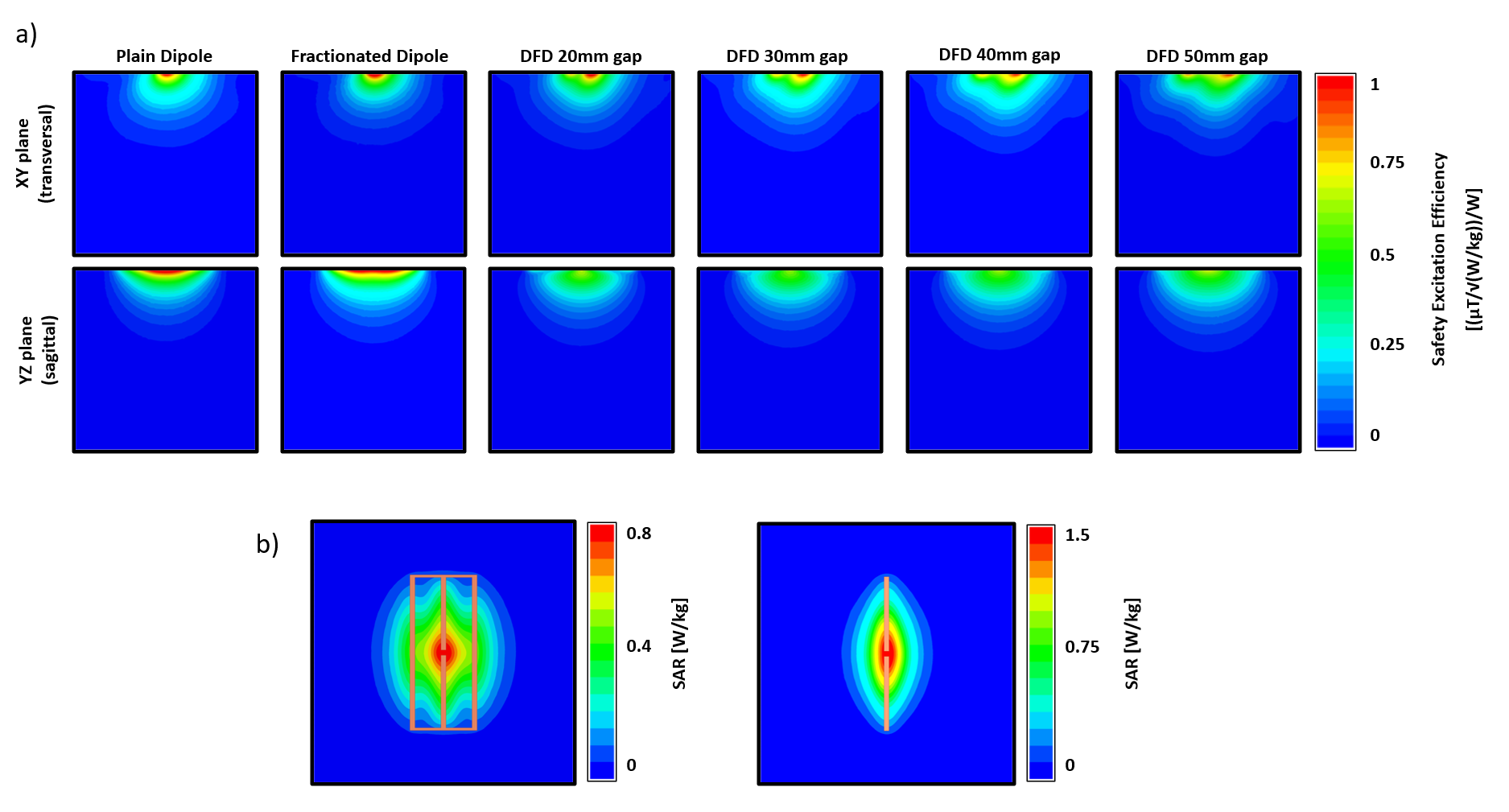
Simulations:Simulations were carried out using a full-wave finite element solver (HFSS, ANSYS, Canonsburg, PA, USA). Four DFD antennas with gaps varying from 20 mm to 50 mm were modeled from copper and centrally placed on a cubical phantom with an offset of 20 mm (Figure 1b). The phantom was dielectrically matched to average tissue properties at 7T (permittivity ε = 34, conductivity σ = 0.4 S/m, density ρ = 1.04 g/cm3). Tuning and matching was achieved with two serial inductors and an integrated lattice balun, respectively. All capacitors and inductors were emulated using lumped ports. For comparison, a regular and a fractionated dipole were also simulated. The new DFD antennas and test dipoles were modeled with a total length of 30 cm, a width of 1 cm, and a 1 cm gapped feed in the center of the dipole. 10g average SAR-values were calculated for 1W accepted input power. B1+ and excitation efficiency values were calculated using the implemented fields calculator in HFSS.
Bench Measurements
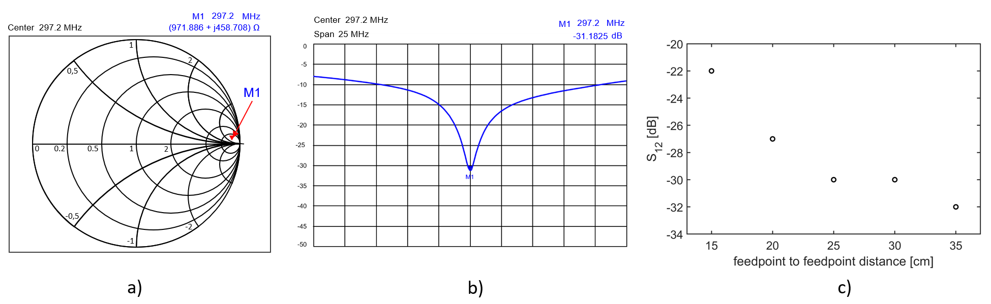
We constructed two DFD antennas with the 50 mm gap from 1.5 mm thick FR4 copper board. A loading phantom was used to match the simulated environment. The antenna’s native impedance was measured with a vector network analyzer (ZNB4, Rhode & Schwarz GmbH & Co. KG, Munich, Germany) (Figure 4). Two hand-wound inductors were incorporated to match the input impedance to 300 Ohm. A lattice balun circuitry was constructed to match from 50 Ohm to 300 Ohm (Figure 1c). The lattice balun was empirically optimized to achieve matching of -30 dB. Geometrical coupling from two adjacent DFD antennas was evaluated with a S21 measure while both antennas were moved towards each other.
Results
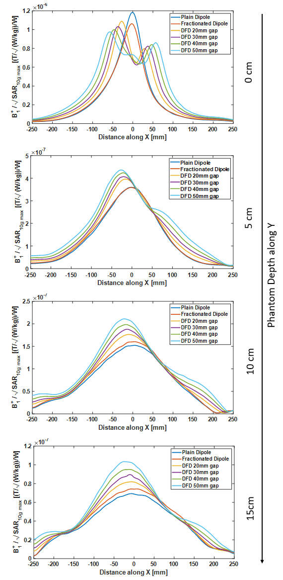
The DFD antenna with the 50 mm gapped ladder structure showed a high input impedance of ~1 kOhm in the simulation. The high impedance could also be verified by an S11 bench measurement. As shown in Figure 2 and 3, at the surface of the phantom, the B1+-to-SAR efficiency (B1+/√SAR10g max) was 18% lower when compared to the sized-matched regular dipole antenna. However, at 5 cm depth, the DFD antenna enables substantial higher B1+-to-SAR efficiency by 21%, and thus, outperforms the regular antenna. With increasing phantom depth, the B1+ efficiency further improves progressively compared to the regular dipole: at 10 cm and 15 cm phantom depth, the gain in efficiency was 38% and 49%, respectively. Bench measurements showed overall low mutual coupling for two adjacent DFD antennas. Leaving a gap of 3 cm, we measured -22 dB remaining coupling while obtaining -18 dB matching at Larmor (Figure 4).Discussion
A double-folded dipole antenna with highly efficiency in B1+ -to-SAR was evaluated with simulations and bench measurements. Only at the proximity under the electric dipole structure, the standard regular dipole antenna outperformed the developed DFD. However, within the first couple of centimeters in the phantom, the DFD antenna equalized the efficiency gain from the regular dipole, and with further phantom depth, substantially more favorable B1+-to-SAR performance could be observed, reaching up to ~1.5-fold improvement. Another advantage was demonstrated by the low mutual coupling of neighboring elements which is likely attributed to the high impedance structure of the antenna. This potentially would allow the construction of a multichannel transmit array with overall low interelement coupling.Conclusion
A double-folded dipole antenna was simulated, and bench tested. The DFD antenna shows highly favorable B1+-to-SAR efficiency. The high impedance structure ensures low mutual coupling between the elements which in turn could allow simple construction of transmit arrays at UHF.Acknowledgements
No acknowledgement found.References
[1] Lattanzi R, Sodickson DK. Ideal current patterns yielding optimal signal-to-noise ratio and specific absorption rate in magnetic resonance imaging: computational methods and physical insights. Magn Reson Med. 2012 Jul;68(1):286-304. doi: 10.1002/mrm.23198. Epub 2011 Nov 29. PMID: 22127735; PMCID: PMC3374920.
[2] Raaijmakers AJ, Italiaander M, Voogt IJ, Luijten PR, Hoogduin JM, Klomp DW, van den Berg CA. The fractionated dipole antenna: A new antenna for body imaging at 7 Tesla. Magn Reson Med. 2016 Mar;75(3):1366-74. doi: 10.1002/mrm.25596. Epub 2015 May 2. PMID: 25939890.
[3] Sadeghi-Tarakameh A, Adriany G, Metzger GJ, Lagore RL, Jungst S, DelaBarre L, Van de Moortele PF, Ugurbil K, Atalar E, Eryaman Y. Improving radiofrequency power and specific absorption rate management with bumped transmit elements in ultra-high field MRI. Magn Reson Med. 2020 Dec;84(6):3485-3493. doi: 10.1002/mrm.28382. Epub 2020 Jun 23. PMID: 32767392; PMCID: PMC7722062.
[4] Oezerdem C, Winter L, Graessl A, Paul K, Els A, Weinberger O, Rieger J, Kuehne A, Dieringer M, Hezel F, Voit D, Frahm J, Niendorf T. 16-channel bow tie antenna transceiver array for cardiac MR at 7.0 tesla. Magn Reson Med. 2016 Jun;75(6):2553-65. doi: 10.1002/mrm.25840. Epub 2015 Jul 17. PMID: 26183320.
[5] Steensma B, van de Moortele PF, Ertürk A, Grant A, Adriany G, Luijten P, Klomp D, van den Berg N, Metzger G, Raaijmakers A. Introduction of the snake antenna array: Geometry optimization of a sinusoidal dipole antenna for 10.5T body imaging with lower peak SAR. Magn Reson Med. 2020 Nov;84(5):2885-2896. doi: 10.1002/mrm.28297. Epub 2020 May 5. PMID: 32367560; PMCID: PMC7496175.
Figures
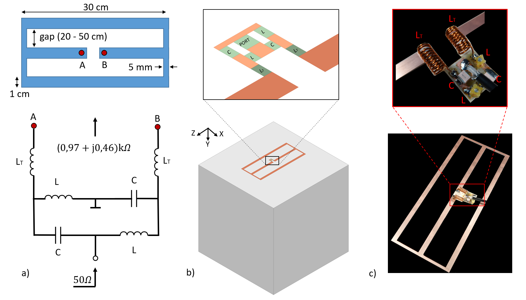
a) geometry of the double-folded dipole antenna and the circuit diagram of the LC lattice balun matching network, b) simulation geometry, c) constructed double-folded dipole antenna with LC lattice balun matching network