1395
An Improved Power Handling Active Transmit/Receive Switch for Low Field MRI using Reed Relays1Athinoula A. Martinos Center for Biomedical Imaging, Massachusetts General Hospital, Charlestown, MA, United States, 2Harvard Medical School, Boston, MA, United States, 3Department of Physics, Harvard University, Cambridge, MA, United States
Synopsis
An active transmit/receive (T/R) switch based on reed relays shows promise in overcoming the previous limitations at low field of both passive and active T/R switches. We aim to provide a design for other low-field researchers to use which handles a wide range of frequencies (DC to 3.4 Mhz) and power levels (<1 mW to 2 kW pulsed) in a simple, low-parts-count device which is easy to reproduce.
Introduction and Justification
MRI in the millitesla regime is an area of active research, promising portability and lower cost1,2 and enabling new applications outside the controlled access radiology suite3,4. However, as previously described5, operation at very low Larmor frequencies (typically < 5 MHz) limits the choices for transmit/receive (T/R) switches which until now have necessitated serious tradeoffs: passive designs often have significant waveform distortion at low power, and active designs without PIN diodes are typically severely limited in power handling.We describe here an improved active T/R switch design that uses reed relays as the switching elements. These devices have long lifetimes (100 million cycles or more, in representative conditions6) due to their sealed construction, as well as off-state isolation of <2 pF and hundreds of volts, and on-resistance of <0.2 ohms6. This is an impressive combination which even Gallium Nitride (GaN) transistors, with currently the best (on-resistance * off-capacitance) metrics of commercially-available solid-state devices, cannot match7. Additionally, the isolation between contacts and relay coil avoids the gate drive complexity required for solid-state solutions. The one disadvantage is the comparatively slow switching time (100s of µs), but this is below the minimum required for many applications.
During development we investigated other options including series-connected GaN transistors, and shunt transistors in between quarter-wave lumped transmission lines, but these alternatives were all found to be inferior in complexity and performance, requiring either: the use of many discrete components, limited transmit pulse widths, high-voltage bias sources, tolerance for excessive distortion, or sensitive performance-limiting manual tuning for each frequency band.
Methods
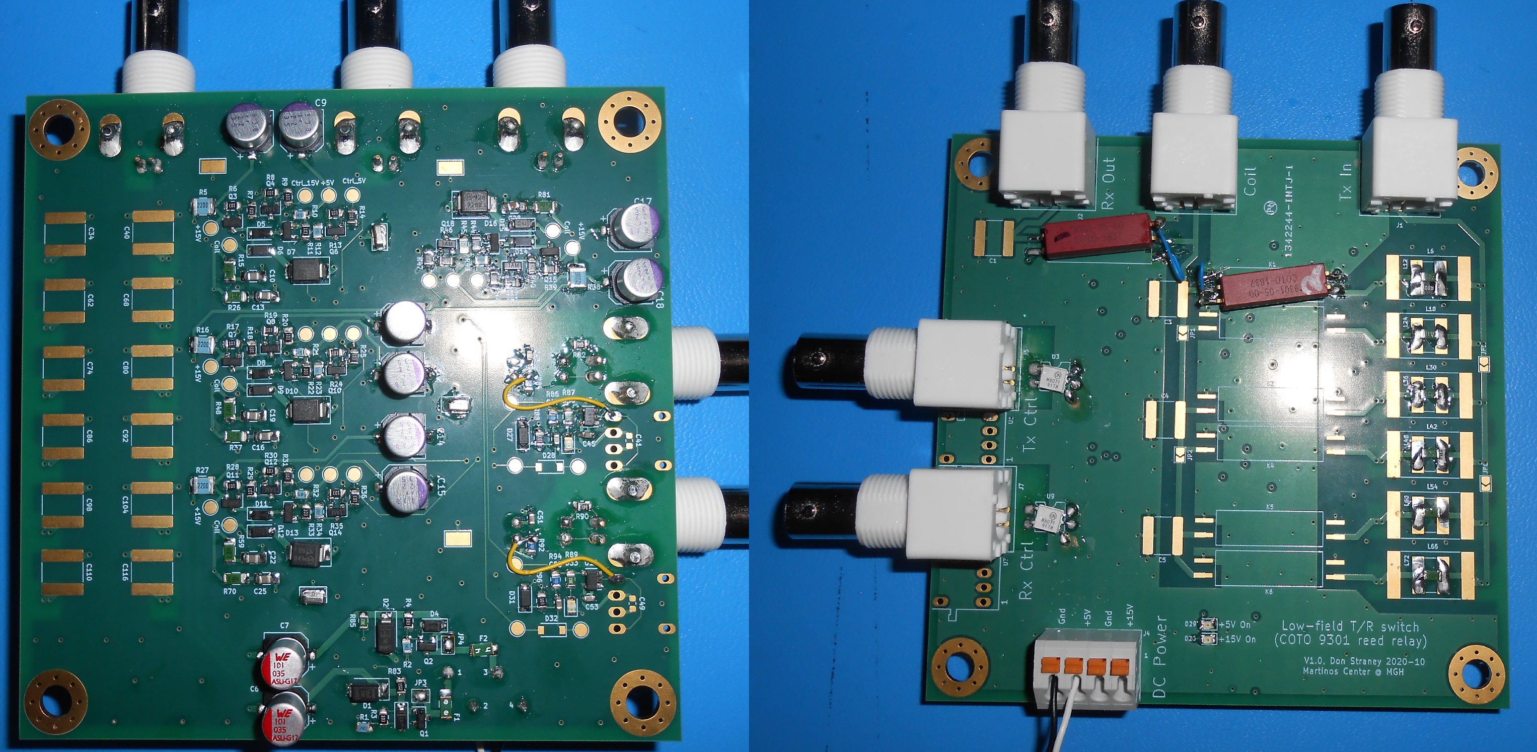
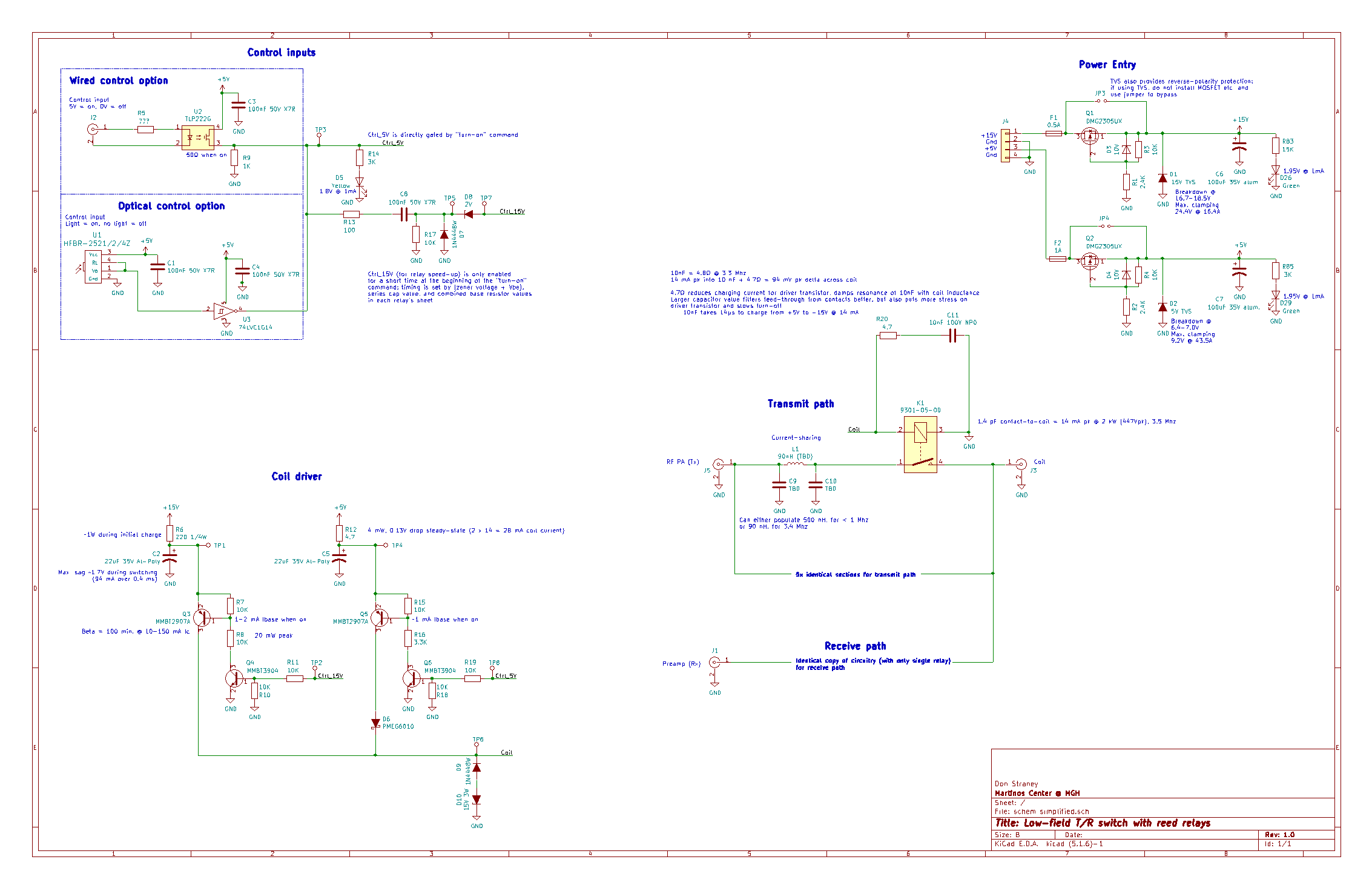
Since most easily-available reed relays are not specified for RF, we first sampled a variety of parts and measured their on-state AC resistance (Rac). This was used together with the DC current rating (Idc) and maximum contact resistance (Rdc) to estimate RF power handling across frequency: when keeping the power dissipation constant, $$$Iac=Idc*√(Rdc/Rac)$$$. Because of the simplified nature of this analysis, and to account for aging, a safety margin of 80-100% on power is then added.The COTO (North Kingstown, RI) 9301-05-00 had the best combination of switching times and power handling of the parts surveyed, so as a proof of concept we created a prototype (Fig. 1, 4) with 1 receive switch and options for up to 6 paralleled transmit switches with a current-sharing scheme for higher power handling.
Design goals include low component count, component availability for easy construction by other researchers, wideband operation (no frequency-specific tuning effort required), and handling operating conditions between, for example, 2 kW, 10% duty cycle @ 3.4 Mhz1 to a few watts at 276 kHz (1H imaging at 6.5 mT) all the way down to <1 mW @ 28 kHz (i.e. for hyperpolarized 15N imaging at 6.5 mT); this wide operating range should make it applicable to many other low-field experiments and scanners.
Results
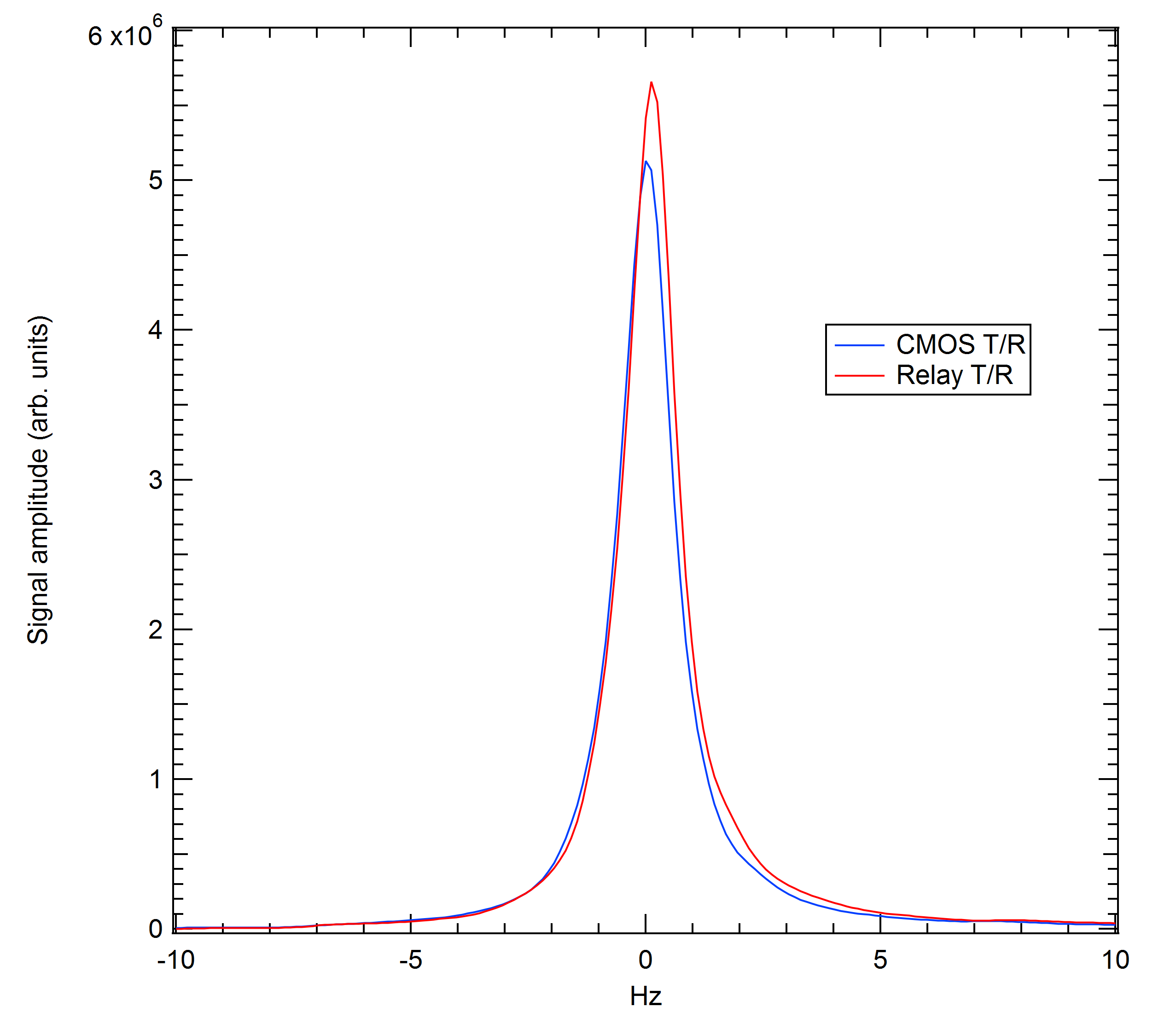
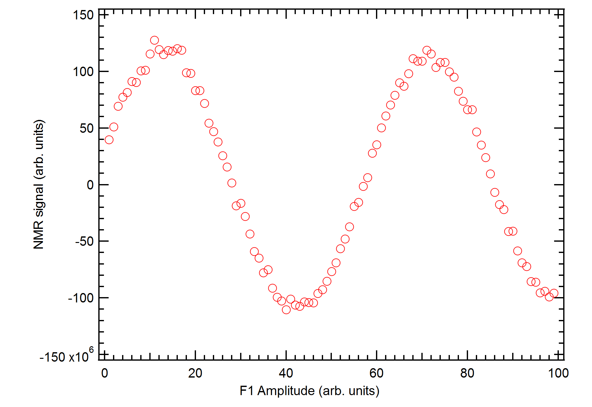
With a single transmit relay installed on the prototype, we measured both transmit and receive paths and found isolation -70 dB or better up to 3.4 Mhz, and insertion loss <0.07 dB (<1%). Tests on the 6.5 mT electromagnet scanner in our laboratory2 in a spectroscopy setup showed good results. When compared against the previously described low-power CMOS T/R switch5, spectroscopic SNR was slightly improved (Fig. 2) at 1341 vs. 1247 (peak height in FT/rms noise of points 1-1000), even at the < 1 mW power levels used in this experiment. This result demonstrates the usability of this approach at the extreme low end of the power range unlike in a passive T/R switch which would distort both the amplitude and phase of the Tx waveform. The transmit calibration nutation curve also showed a clean sinusoidal response as expected (Fig. 3). The magnetic shielding on each relay successfully isolated the scanner B0 field from the relay coils’ magnetic fields, and the switching circuitry did not add to the measured noise floor.As for the high-power capabilities, the receive relay is rated to stand off 500V in transmit mode, enough for 2 kW pulsed plus headroom, and the AC resistance measurements show that each relay should handle at least 0.63A RMS at 3.4 Mhz, which is 20W of continuous power (or 200W at 10% transmit duty cycle) into 50Ω. Power handling is much higher at lower frequencies, with an estimated 48W continuous (480W at 10% transmit duty cycle) at 300 kHz. Full-power tests are still in process due to earlier scheduling difficulties.
Switching time is currently <400µs, but a speed-up circuit under development shows promise for reducing this to an estimated <200µs.
Next Steps
Although the rated lifetime of these reed relays has orders of magnitude beyond what would be required, it is unclear what the exact end-of-life conditions would be for a low-field application as opposed to the manufacturer tests. To fully understand the degradation over time and create a realistic "parts-swapping schedule", more thorough lifetime testing needs to be done, especially with pulsed RF loads. We plan on creating a test fixture to rapidly cycle a set of relays under worst-case conditions and investigate failure modes this way.We will also release detailed documentation so that other researchers can easily build copies for their own systems.
Acknowledgements
We would like to thank Charlotte Sappo for the discussions and her previous research on this topic.
We acknowledge support from the Advanced Research Projects Agency-Energy (ARPA-E), U.S. Department of Energy, under Award Number DE-AR0000823 for contributing to fund the information, data, or work presented herein. The views and opinions of authors expressed herein do not necessarily state or reflect those of the United States Government or any agency thereof.
References
- Cooley CZ, McDaniel PC, Stockmann JP, Srinivas SA, Cauley SF, Śliwiak M, Sappo CR, Vaughn CF, Guerin B, Rosen MS, Lev MH, Wald LL. A portable scanner for magnetic resonance imaging of the brain. Nat Biomed Eng. 2020. Epub ahead of print. PMID: 33230306.
- M. Sarracanie, C. D. LaPierre, N. Salameh, D. E. J. Waddington, T. Witzel, and M. S. Rosen, “Low-Cost High-Performance MRI,” Sci Rep, vol. 5, no. 1, p. 15177, Oct. 2015.
- K. N. Sheth, M. H. Mazurek, M. M. Yuen, B. A. Cahn, J. T. Shah, A. Ward, J. A. Kim, E. J. Gilmore, G. J. Falcone, N. Petersen, K. T. Gobeske, F. Kaddouh, D. Y. Hwang, J. Schindler, L. Sansing, C. Matouk, J. Rothberg, G. Sze, J. Siner, M. S. Rosen, S. Spudich, and W. T. Kimberly, “Assessment of Brain Injury Using Portable, Low-Field Magnetic Resonance Imaging at the Bedside of Critically Ill Patients,” JAMA Neurol, Sep. 2020.
- G. C. Bagnall, N. Koonjoo, S. A. Altobelli, M. S. Conradi, E. Fukushima, D. O. Kuethe, J. E. Mullet, H. Neely, W. L. Rooney, K. F. Stupic, B. Weers, B. Zhu, M. S. Rosen, and C. L. S. Morgan, “Low-field magnetic resonance imaging of roots in intact clayey and silty soils,” Geoderma, vol. 370, p. 114356, 2020.
- Sappo CR, Martin MN, Shen S, Koonjoo N, Kos AB, Grissom WA, Rosen MS, Stupic KF, "Active Transmit/Receive Switches for Low Field Magnetic Resonance (<100mT)". International Society for Magnetic Resonance in Medicine 2020 #4067
- "9300-9400 Series/Surface Mount Reed Relays", https://www.cotorelay.com/product/9300-9400-series-surface-mount-reed-relays/
- "GS-065-011-1-L 650 V E-mode GaN transistor Datasheet", https://gansystems.com/wp-content/uploads/2020/09/GS-065-011-1-L-DS-Rev-200922.pdf; (Fig. 7 on p.6 shows Coss > 100pF @ 0V for this 150mΩ part)
Figures