1394
High Impedance Loop coil Design for improved EM Decoupling in Multichannel Coil arrays1University at Buffalo, Buffalo, NY, United States, 2Biomedical Engineering, University at Buffalo, Buffalo, NY, United States
Synopsis
In traditional magnetic resonance imaging (MRI) design, ideal coil overlapping is used to minimize coupling between nearest-neighbor coils, and low input impedance preamplifiers are used to isolate the relatively weak coupling. Modern-day MR systems use phased array coils constructed out of low impedance resonant loops. Inside such arrays, electrodynamic interactions between elements must be carefully balanced[1]. However, to make the complex sensitivities of phased-array coils sufficiently distinct in parallel spatially-encoded MRI, needed an overlapping between coils. This electromechanical balancing act becomes increasingly difficult as the number of receive elements grows for optimal performance, leading to geometrical puzzles of profound complexity.
Introduction
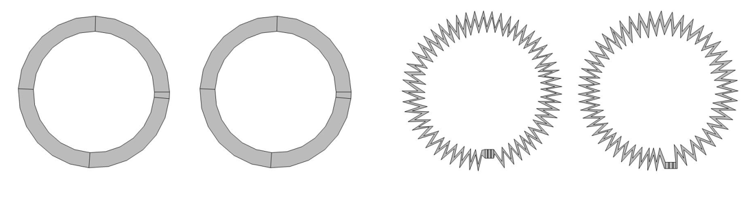
We design a coil array using high impedance coil (HIC) based on the zig-zag inductor strategy for acquiring MR signals and evaluate B1 fields from a parallel non-overlapping and closely positioned zig-zag inductor circular RF coils which show the coupling and decoupling effect between the coils. So, this coupling effect can be reduced when the circular surface coils placed parallel to each other and the coils are designed in such a way that by increasing the length of the coil without effecting the radius we make a zig-zag (saw tooth) shaped circular coils as shown in Fig.1. This increases the length, resulting in an increased impedance of the coil elements, and consequently decreasing the coupling between each other. Here a couple and decoupling theory are introduced to provide a better understanding of the relations between coupled and uncoupled signals in the MRI circular RF coil system, and offer a new method for decoupling parallel coils without overlapping and also any decoupling network.Methods
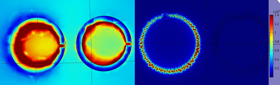
The high impedance circular coil was described by designing and comparing with two dimensional parallel circular coils with a radius of 5cm and the thickness of the coil is 1cm alongside the two circular coils were separated by a distance of 1cm. This design shows a noticeable amount of coupling on the second coil when the first coil was given power. The B1 fields were collected and the resonant frequency of 7Tin the COMSOL software and the impedance was also noticed. So, in order to show the decoupling, we design a similar parallel circular coil array with the same radius and the width of the coil is varied as we design it in the shape of sawtooth. The two circular coils were separated by same distance 1cm. Now by applying the same frequency with the similar approach we attain the B1 fields for the circular coils, but here the coupling effect is completely not seen because of the variation in the length with respect to the design of the coil. Numerical simulations and analysis of the integrated coil system were conducted by COMSOL Multiphysics Technology, (Stockholm, Sweden). A Frequency-domain solver was employed and with the solver accuracy to -40 dB in the EM simulations. We create a mesh for the geometry that we designed for the organized E1, B1 field distributions. The boundaries of the RF coil are all set open and the frequency was set to 300 MHz. The Eigen frequency solver was employed at the frequency around 7T and the Electric and Magnetic field distributions were observed. The performance of the proposed High-impedance coil array was evaluated by B1 field and various parameters in the EM simulations. The B1 field was solved based on the accepted power normalized to 1W for each coil. The B1 fields of the HIC were reconstructed and analyzed.Results
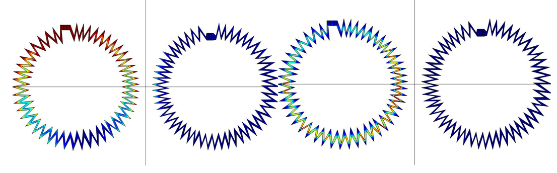
The difference in design, electric and magnetic fields of the high impedance circular coils are obtained and shown in Fig.3. The resonant frequency of both the coil models was calculated and they should be maintaining same frequency beside makes sure the range of the B1 fields should also be same in order to compare the coupling and decoupling. Both the coils were operated at same current for the high impedance output. The simulated B1 fields of the HIC were calculated as shown in the Fig.3.Discussion/ conclusion
In this work, this new method for designing decoupled coil array elements using zig-zag inductor strategy is proposed and investigated. The improved decoupling performance of the proposed design is observed. This zig-zag inductor surface coil design can be used as a building block for multichannel coil arrays with a large channel count.Acknowledgements
No acknowledgement found.References
1. Sanchez-Heredia JD, Johansen DH, Hansen RB, Szocska Hansen ES, Laustsen C, Zhurbenko V, Ardenkjaer-Larsen JH. Improved Decoupling for Low Frequency MRI Arrays using Non-conventional Preamplifier Impedance. IEEE Trans Biomed Eng. 2018 Nov 13. doi: 10.1109/TBME.2018.2881203. Epub ahead of print. PMID: 30442598.Figures