1393
Performance of flexible coaxial transmission line resonator coils vs. stranded wire coils at 3 T
Raphaela Czerny1, Michael Obermann1, and Elmar Laistler1
1High Field MR Center, Center for Medical Physics and Biomedical Engineering, Medical University of Vienna, Vienna, Austria
1High Field MR Center, Center for Medical Physics and Biomedical Engineering, Medical University of Vienna, Vienna, Austria
Synopsis
As flexible form-fitting RF coils can provide enhanced receive sensitivity in MRI, various coil design approaches have been studied recently, including coaxial and stranded wire coil elements. While stranded wire coils are electrically identical to conventional rigid copper loop coils, coaxial transmission line resonators are self-resonant and do not require additional components along the conductor. The goal of this work was to compare flexible receive-only stranded wire coils and coaxial coils in terms of Q-factors, inter-element coupling, noise correlation, and SNR.
Introduction
Improvement of receive sensitivity in MRI with high inter-patient variability demands creative and adaptive design approaches such as flexible RF coil elements. Recent developments towards the “one-coil-fits-all” principle comprise stranded wire coils (SWC)1 and coaxial transmission line structures (CC)2,3, demonstrating promising results regarding SNR or inter-element coupling.In this work, we present a comparative study between flexible receive-only SWC and CC designs for 3T MRI. While both cable types provide a flexible design, their physical characteristics differ. SWCs behave similarly to standard copper loop coils (SC): equivalent interfacing can be used and tuning of the resonance frequency is accomplished by capacitors segmenting the loop. In contrast, CCs with a gap in outer and inner conductor are self-resonant structures, tuned by their geometric properties. No additional lumped components along the conductor are required. A single channel SWC, CC and SC were fabricated and studied. The performance of the coil designs was compared in terms of Q-factors and SNR. Additionally, a 4-channel SWC was built and compared to a 4-channel CC regarding inter-element coupling and noise correlation.
Methods
Coil and interface development:For the coil fabrication, ÖLFLEX®HEAT260SC (LAPP Austria GmbH, Linz, Austria) stranded wire, Temp-Flex100193-5047 (Molex Inc., Lisle, USA) coaxial cable and rigid copper wire were employed, each with a conductor diameter between 1-1.1mm. All coil elements are 8cm in diameter. CCs have one gap in outer (opposite to coil port) and inner (at coil port) conductor and are self-resonant close to the Larmor-frequency. SWCs and SCs were segmented once by a tuning capacitor opposite to the coil port. Low-noise preamplifiers (MPB-123R20-90, HI-Q.A. Inc, Ontario, Canada; MSM-123281, Microwave Technology Inc, Fremont, CA, USA) were used. 4-channel arrays with respective coil interfaces are shown in Fig.1.
Bench measurements:
For each coil, $$$S_{ii}$$$ was measured on a VNA (E5071C, Agilent, Santa Clara, CA, USA) to verify tuning and matching (all < -14 dB). A 5‑l container phantom for measurements in flat and a 3‑l balloon in bent configuration (bending radius≈6.5cm), filled with saline solution (DC-conductivity=0.2S/m) doped with 1ml/l Gd, were used. Single loop coils were directly fixed on it, whereas 3mm separated the coil arrays and sample. Q-factors of single loop coils were measured without interface in unloaded and loaded configuration via double-loop probe4. Inter-element coupling was determined by measuring the $$$S_{ij}$$$‑parameter matrix. Preamplifier decoupling was measured via double-loop probe by calculating the $$$S_{21}$$$-parameter difference with the coil connected to the preamplifier vs. 50Ω termination.
MRI measurements:
MRI tests were performed on a 3T scanner (Magnetom Prisma-Fit, Siemens Healthineers, Erlangen, Germany). With data acquired by GRE sequences (TR/TE=50/10ms, 0.6x0.6mm2 resolution, 6.5mm slice thickness, FOV=290x290mm2), SNR maps of the 1-channel coils with the 5-l phantom were calculated in MATLAB R2020a (The MathWorks, Inc., Natick, MA, USA). A circular ROI with a 1cm radius was defined, with the center of the circle located 1.5cm under the coil center. For calculation of 4-channel array noise correlation matrices, noise-only scans without excitation pulse were performed with the 5-l phantom (3mm coil-sample distance).
Results
Bench measurements:Results of the bench measurements of single loop SWC, CC and SC are shown in Fig.2. Significantly lower unloaded Q-factors were found for the CC, resulting in lower Q-ratios. Nevertheless, Q-ratios > 5.5 were achieved for all coil types and configurations, indicating sample noise dominance. Results of geometric and preamp decoupling of the arrays are depicted in Fig.3. As expected, highest coupling was found between non-overlapping coil elements (1 and 3). Inter-element coupling remained in the same range for SWC and CC arrays.
MRI measurements:
SNR maps of the 1-channel coil designs are presented in Fig.4. Compared to the SC, the mean SNR in the ROI was 4% lower for the flexible SWC and 9% lower for the CC. The noise correlation matrices of the 4-channel arrays are shown in Fig.5. The mean noise correlation is 0.3±0.1 for SWC and 0.2±0.1 for CC. Analogously to the bench measurement results, the highest correlation was found between channels 1 and 3.
Discussion
Lower Q-factors were observed for CC elements than for SWC or SC, however, all coils were clearly sample-noise dominated. The SNR of single loops of both flexible coil types were only slightly lower compared to the SC. This small drawback could maybe be attributed to lower conductivity but is easily compensated by better form-fitting.4-channel SWC and CC arrays showed similar geometric and preamp decoupling on the bench. Noise correlation was slightly higher for SWC. The requirement of mechanical flexibility is satisfied by both coil designs, however, solder joints for tuning capacitors on SWCs pose a possible breaking point of the coil. SWCs have the advantage that all standard interfacing technology can be used the same way as for rigid standard loops. Further MR measurements of the 4-channel arrays including SNR mapping are in process.
Conclusion
Stranded wire coils and coaxial coils both have only slight SNR disadvantages (-4% and -9%) against rigid loops but allow form-fitting to the sample. Main differences are additional breaking points by soldering of the segmenting capacitor in SWCs, and non-standard interfacing of CCs. The choice between SWCs and CCs is therefore not entirely driven by coil performance but rather practical considerations.Acknowledgements
This work was funded by the Austrian/French FWF/ANR grant, No. I-3618, “BRACOIL“.References
- Roat S, Vít M, Wampl S, Schmid AI, Laistler E. A Flexible Array for Cardiac 31P MR Spectroscopy at 7 T. Front. Phys. 2020;8:92.
- Zhang B, Sodickson DK, Cloos MA. A high-impedance detector-array glove for magnetic resonance imaging of the hand. Nat. Biomed. Eng. 2018;2:570-577.
- Ruytenberg T, Webb A, Zivkovic I. Shielded-coaxial-cable coils as receive and transceive array elements for 7T human MRI. Magn. Reson. Med. 2020;83(3):1135-1146.
- Darrasse L, Kassab G. Quick measurement of NMR-coil sensitivity with a dual-loop probe. Rev. Sci. Instrum. 1993;64:1841-1844.
Figures
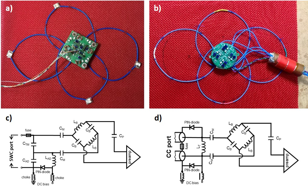
Figure 1: 4-channel
stranded wire coil array (a) and coaxial coil array (b) sewn onto fabric to maintain
coil overlap for optimal geometric decoupling. PIN bias cables are connected to
coil interfaces in the middle. In (b) a floating cable trap used in both setups
is shown. Circuit diagrams of coil interfaces are shown below for SWC (c) and
CC array (d), containing tuning, matching, active detuning, balun, phase
shifter, fuse and preamplifier. 1-channel coil interfaces did not include balun,
phase shifter and fuse.
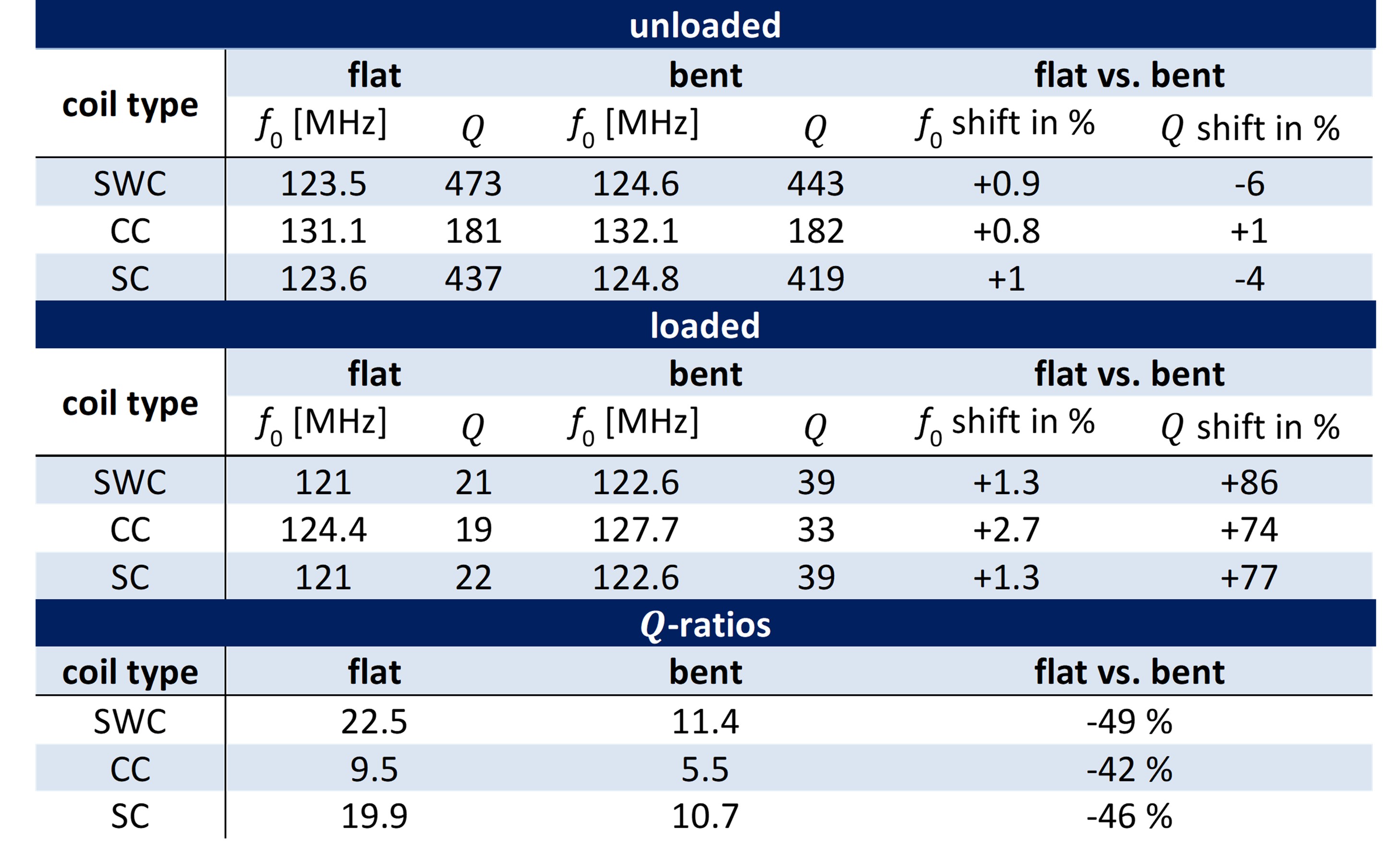
Figure 2: Unloaded
(without phantom) and loaded (with phantom) bench measurements with the three 1-channel
coils: Resonance frequency f0, Q-factor and Q-ratios in flat and bent configurations and
their deviations due to bending. Flat phantom: 5-l tank, bent phantom: 3-l
balloon.
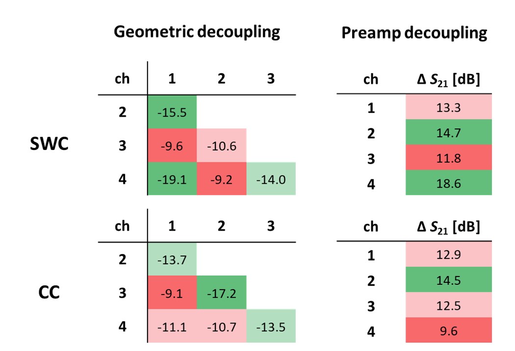
Figure 3: Geometric decoupling of SWC and CC (left): Sij-parameters
in dB between the coil channels. Preamplifier decoupling of SWC and CC (right):
S21-parameter difference
(coil connected to powered preamp vs. 50 Ω termination) in dB measured with a double-loop probe. A color code
was used to indicate low decoupling in red and high decoupling in green.
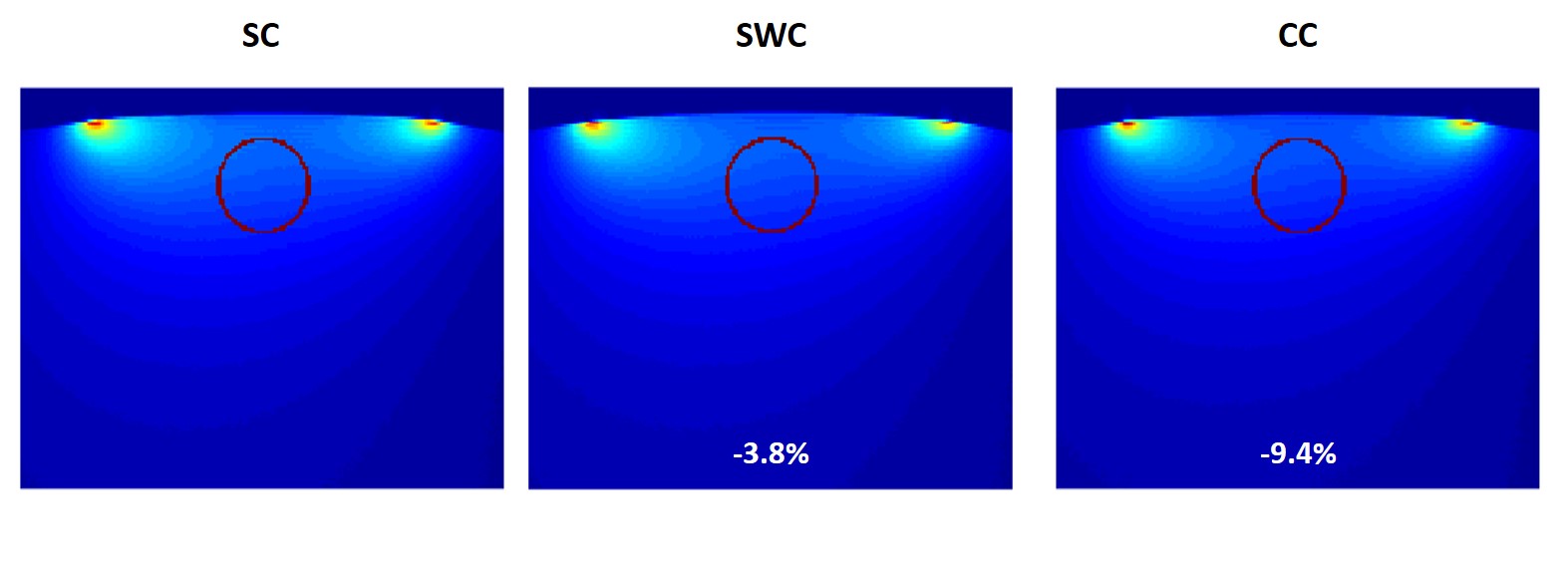
Figure 4: 3T
MRI measurements: SNR maps in the central transversal slice of the 1-channel SC
(left), SWC (middle) and CC (right) with a 5-l container phantom acquired from
GRE sequences. The red circle indicates the chosen ROI, where the mean SNR was
calculated. Relative comparison of the SNR to the SC in the ROI is given for the SWC and CC.
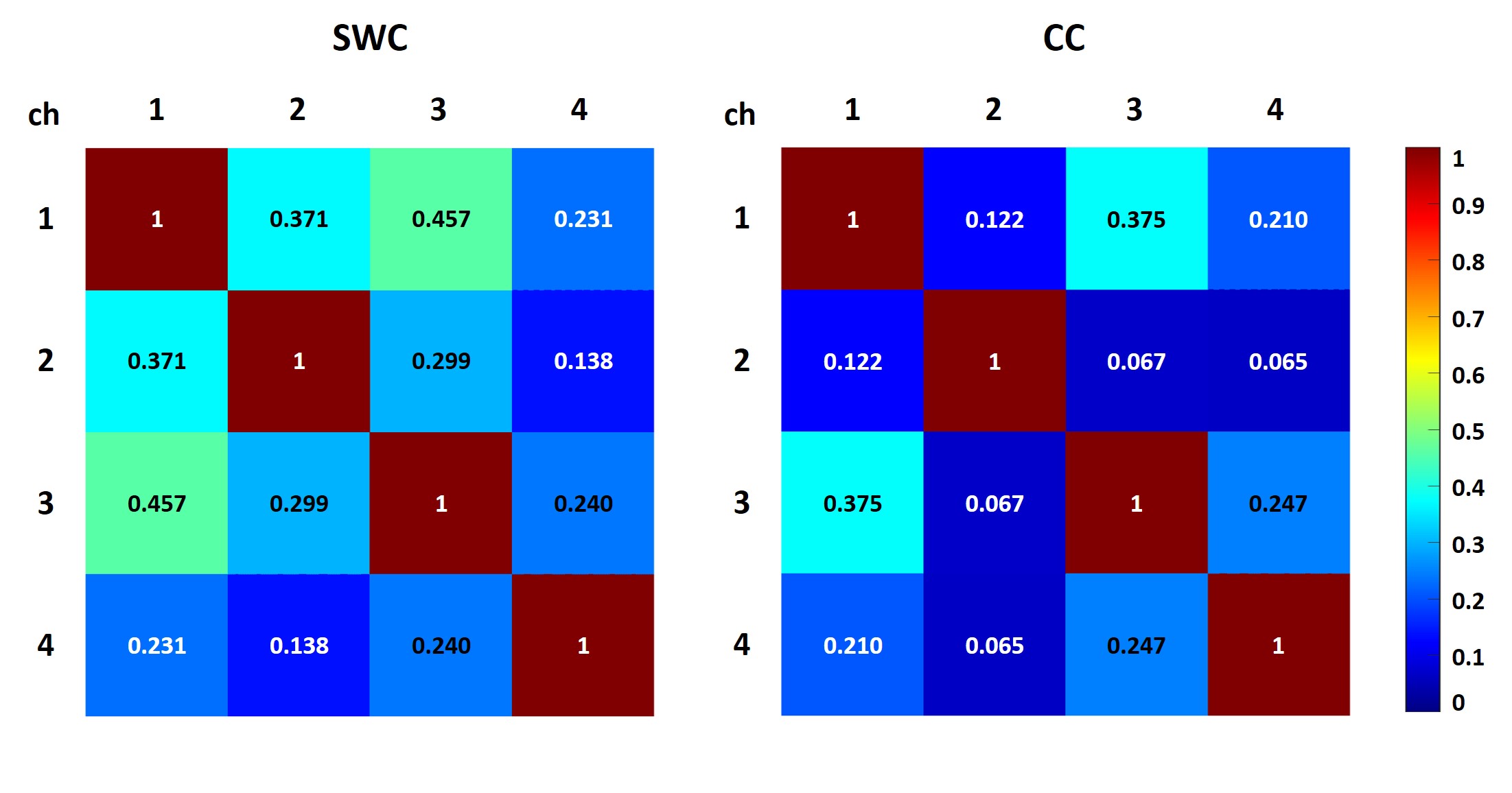
Figure 5: Noise
correlation matrix of the 4 channel receive elements of the stranded wire coil
(left) and the coaxial coil (right) ranging from 0 (no correlation) to 1
(highest correlation).