1392
Bailey splitter/combiner for RF shimming/Rx coil combination1Vanderbilt University Institute of Imaging Science, Nashville, TN, United States, 2Department of Radiology and Radiological Sciences, Vanderbilt University, Nashville, TN, United States, 3Biomedical Engineering, Vanderbilt University, Nashville, TN, United States, 4Electrical and Computer Engineering, Vanderbilt University, Nashville, TN, United States
Synopsis
We designed a continuously adjustable Bailey splitter/combiner with a sliding mechanism. This device has a good input matching of < -18dB and a low insertion loss of about -0.5dB. The sliding mechanism allowed easy handling and precise adjustments. The resistor free design eliminated the potential safety concern from the previous Ratio Adjustable Power Splitter circuits. We obtained good agreements between predicted and measured transmit field maps with the Bailey splitter/combiner.
Purpose
It is increasingly available for both transmit and receive array to be built with many independent coil elements with modern coil technologies and advanced decoupling methods [1-5]. However, the independent transmit channels and receive channels are limited. One possible solution is to have many transmit coils compressed to a few transmit channels or receive channels [6-8]. A power splitter/combiner will be needed to realize such array-compressed networks. A well-known example is the Wilkinson splitter and its variants. The 100-Ohm resistor in the Wilkinson splitter might bring safety concerns in the transmission chain while it could degrade SNR in the receive chain. We introduced a resistor free RF splitter/combiner, namely Bailey splitter/combiner [9], to address these problems in this work.Methods
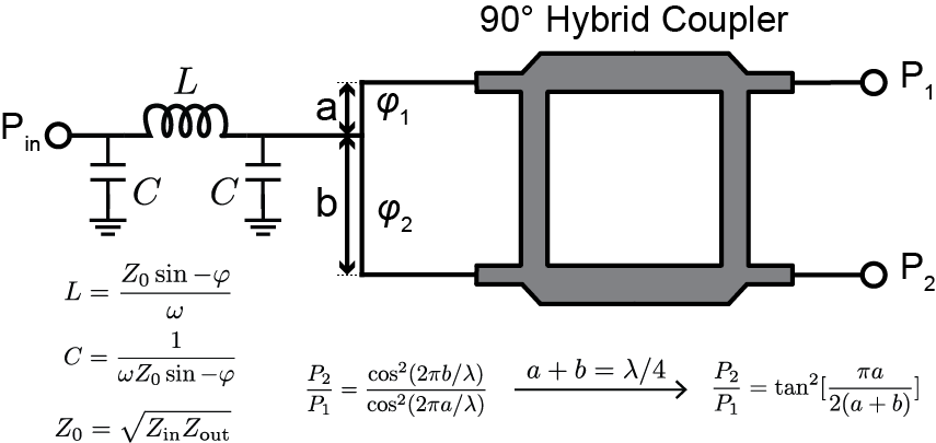
TheoryFigure 1 shows the circuit diagram of the Bailey splitter/combiner. For simplicity, we will only mention it as Bailey splitter in the following sections (a combiner is achieved by reversing the signal flow direction). This splitter is composed of a pi-shaped matching network, a microstrip line, and a hybrid coupler. The split ratio can be adjusted by sliding the contact point on the microstrip line (with the split lengths of a and b). When a+b = λ/4, where λ is the wavelength of the signal, the power splitting ratio is $$$\tan^2(\frac{\pi a}{2(a+b)})$$$.
Fabrication and Evaluation
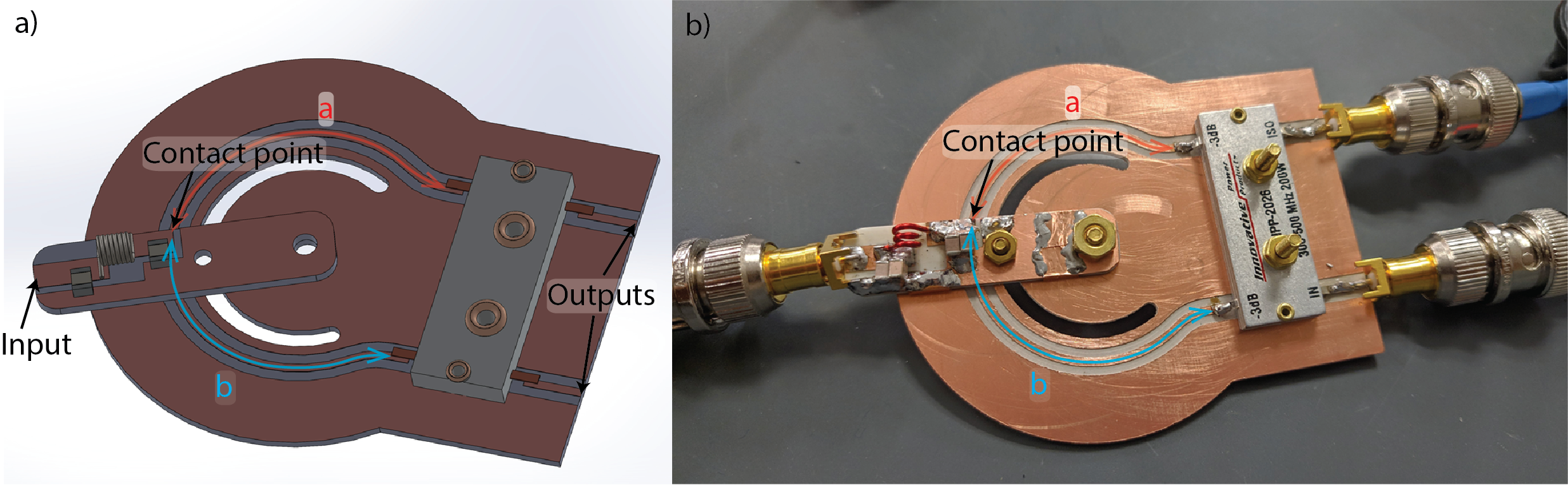
The Bailey splitter was fabricated on a low-loss PCB board (motherboard, Rogers 3010, dielectric constant 10.2, and board thickness 1.27 mm).A microstrip trace connected two input ports of a commercial hybrid coupler (IPP2026, Holbrook, NY). The electric length at 298 MHz (the Larmor frequency of 7 T) of this trace is slightly longer than 90 degrees to enable arbitrary split ratio (Based on equations in Figure1). The impedance matching circuit is equivalent to a 90-degree transmission line that converts 25-Ohm impedance to 50 Ohm. It is built on a small removable PCB (Rogers 4003C daughterboard), with two 6.8 pF capacitor (1111C series, PPI, Huntington, NY) and a hand-wound air-core inductor (~18 nH). Figure 2 shows the Solidworks drawing and the photograph of a Bailey splitter.
MR experiments
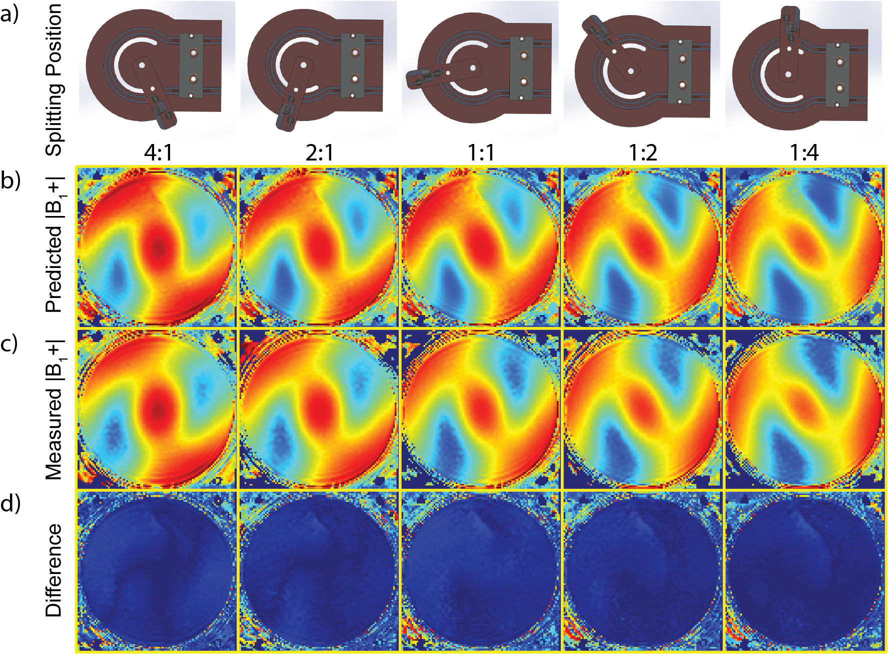
To validate the splitter’s bench test results and evaluate its performance in MRI applications, we performed transmit field (B1+) maps experiments on a 7 T human scanner (Philips, Amsterdam, Netherlands) using the DREAM method (TR 1000 ms, FOV 16x16 cm2, voxel size 2x2 mm2, slice thickness 10 mm). B1+ maps of I and Q ports of the Nova birdcage coil were measured with one transmit channel. By inserting the Bailey splitter, the transmit channel's RF power was split to the I and Q ports of the Nova coil. For each split ratio, we measured the B1+ map and compared it to the predicated map based on the bench test results.
Results and discussion
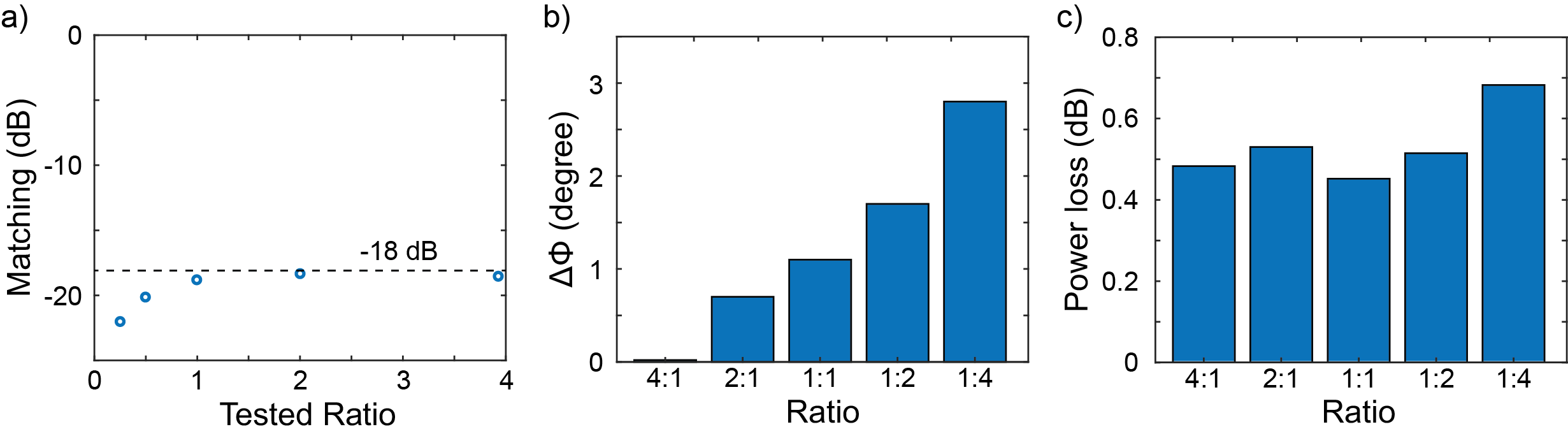
The bench test results of the fabricated device are shown in Figure 3. To achieve the desired power splitting ratios, we manually adjusted the contact point by checking the Sin1 Sin2 values in a Vector Network Analyzer (Keysight, Santa Rosa, CA). The matching board was then fastened to the motherboard. We found that it took only around one minute adjusting to each ratio ( 1:4, 1:2, 1:1, 2:1, and 4:1). The measured ratios in bench tests are 1:3.99, 1:2.01, 1:1.00, 2.00:1 and 3.93:1. The impedance matching of the input port (Figure 3a) is always lower than -18 dB. Unlike RAPS circuits, Bailey splitter is an in-phase splitter where the phase differences between two outputs are less than 3 degrees across different ratios. The insertion loss of the whole circuit (Figure 3c) is around -0.5 dB, and it could further be reduced by using an improved design of the contacting point.MR experiments (Figure 4) compared the measured B1+ amplitude maps with the predicted maps. The small difference between the predicted and measured B1+ maps indicates that this Bailey splitter works well in RF shimming. Likewise, it should have a similar performance in the receive coil combination. This device was not influenced by the static or gradient magnetic fields when placed close to the RF coils due to its compact dimensions and non-magnetic components.
Compared to the Wilkinson splitter and the previously reported RAPS [10], this circuit eliminates the need for the RF resistor. We designed an easier-to adjust mechanism by sliding, which is desirable in the initial RF shimming tests/evaluations, where the power-split ratio may be changed many times before achieving the optimal performance. Although the Bailey splitter's two outputs are not matched or isolated like the T-junction splitter, we found it not affecting the RF shimming performance. Further studies are needed to investigate whether the power-split ratio will deviate from the expected values in extreme cases, such as strongly coupled and mismatched RF coils due to component failure or large loading variations.
Conclusion
A Bailey Splitter/combiner was introduced for MRI application. It is resistor-free and has a universal design that eliminates the need for additional components. The power-split ratio could be continuedly adjusted by simply sliding the input board. Theoretically, it can realize arbitrary power-split/combination ratios. Bailey splitter’s performance was validated in bench tests as well as in MRI experiments.Acknowledgements
No acknowledgement found.References
1. Wiggins GC, Potthast A, Triantafyllou C, Lin FH, Benner T, Wiggins CJ, Wald LL. A 96-channel MRI system with 23-and 90-channel phase array head coils at 1.5 Tesla. In Proceedings of the 13th Annual Meeting of ISMRM, Miami Beach, FL, USA 2005 (p. 671).
2. Schmitt M, Potthast A, Sosnovik DE, Polimeni JR, Wiggins GC, Triantafyllou C, Wald LL. A 128‐channel receive‐only cardiac coil for highly accelerated cardiac MRI at 3 Tesla. Magnetic Resonance in Medicine: An Official Journal of the International Society for Magnetic Resonance in Medicine. 2008;59(6):1431-9.
3. Lee RF, Giaquinto RO, Hardy CJ. Coupling and decoupling theory and its application to the MRI phased array. Magnetic Resonance in Medicine: An Official Journal of the International Society for Magnetic Resonance in Medicine. 2002;48(1):203-13.
4. Connell IR, Gilbert KM, Abou-Khousa MA, Menon RS. Design of a parallel transmit head coil at 7T with magnetic wall distributed filters. IEEE transactions on medical imaging. 2014;34(4):836-45.
5. Yan X, Gore JC, Grissom WA. Self-decoupled radiofrequency coils for magnetic resonance imaging. Nature communications. 2018;9(1):1-2.
6. Buehrer M, Pruessmann KP, Boesiger P, Kozerke S. Array compression for MRI with large coil arrays. Magnetic Resonance in Medicine: An Official Journal of the International Society for Magnetic Resonance in Medicine. 2007;57(6):1131-9.
7. King SB, Varosi SM, Duensing GR. Optimum SNR data compression in hardware using an Eigencoil array. Magnetic Resonance in Medicine. 2010;63(5):1346-56.
8. Cao Z, Yan X, Grissom WA. Array-compressed parallel transmit pulse design. Magn Reson Med. 2016;76:1158-1169.
9. Bailey M C. a simple stripline design for uneven power split. NASA Technical Reports Server. 1982;6:31684-31693
10. Yan X, Cao Z, Grissom WA, Ratio-adjustable power splitters for array-compressed parallel transmission. Magn Reson Med. 2018;79:2422–2431
Figures