1391
The Coax Dipole Antenna: a flexible, low SAR dipole antenna for body imaging at 7 Tesla.1University Medical Center Utrecht, Utrecht, Netherlands, 2Biomedical Engineering, Eindhoven University of Technology, Eindhoven, Netherlands
Synopsis
A coax cable dipole antenna with gaps in the shield supports flat current profiles on the outside of the shield. A simulation study is performed to further optimize the design of this flexible so-called ‘coax dipole antenna’. MR thermometry measurements are performed using a single antenna and a homogeneous phantom. The coax dipole antenna causes 18% lower peak heating than a fractionated dipole antenna. An array of eight coax dipole antennas is used to generate T2-weighted images and B1 maps of the prostate of three volunteers, where the coax dipoles achieve the same B1 as an array of fractionated dipoles.
Introduction
Dipole antennas are commonly used transmit/receive elements for ultra-high field MRI1. Different strategies can be used to optimize the antenna performance for body2 and brain imaging3,4 or to decrease local peak SAR5-10. Recently, the use of shielded coaxial loop coils has been demonstrated to achieve improved decoupling11-13, lower peak SAR14 and a flexible coil design which allows for better coil loading compared to rigid loop coils. In this work, we investigate whether we can apply the same principle in dipole antennas to improve the overall performance. We investigated this concept through simulations and designed a coaxial dipole with a flat current distribution on the outer shield of the coaxial cable. In addition, the design minimizes losses and facilitates matching. A transceive array of eight coax cable dipole antennas was built and successfully tested in-vivo.Methods
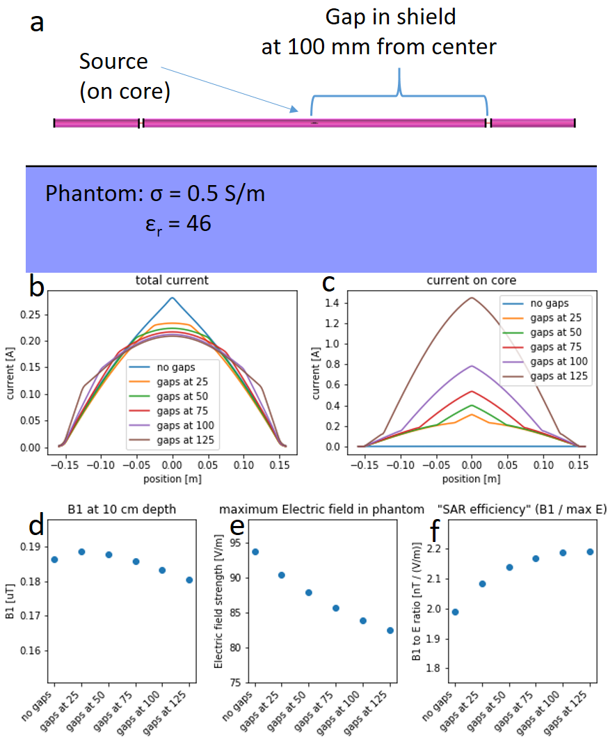
A coaxial cable dipole antenna, driven on the core (central conductor) of the cable, is shielded and therefore does not radiate. However, if the shield (outer conductor/mantle) of the cable is interrupted by gaps, current will flow towards the outside of the shield and the antenna becomes effective. FDTD simulations (Sim4Life, Zurich Medtech, Switzerland) were used to investigate what effect the position of these gaps has on the current distribution, B1 amplitude and peak electric field value. Next, we investigated the effect of adding a lumped element to each end of the antenna. After determining the optimal gap position and lumped element value, eight antennas (figure 3) were constructed out of coaxial cable. Single antenna B1 maps and MR Thermometry measurements on a homogenous phantom (σ=0.5 S/m, εr=4615) were used for comparison to a standard fractionated dipole antenna. To study its effectiveness in an array setup, B1 maps were acquired from the prostate region for three healthy volunteers using the coaxial cable dipole array and fractionated dipole antennas2 for comparison.Results
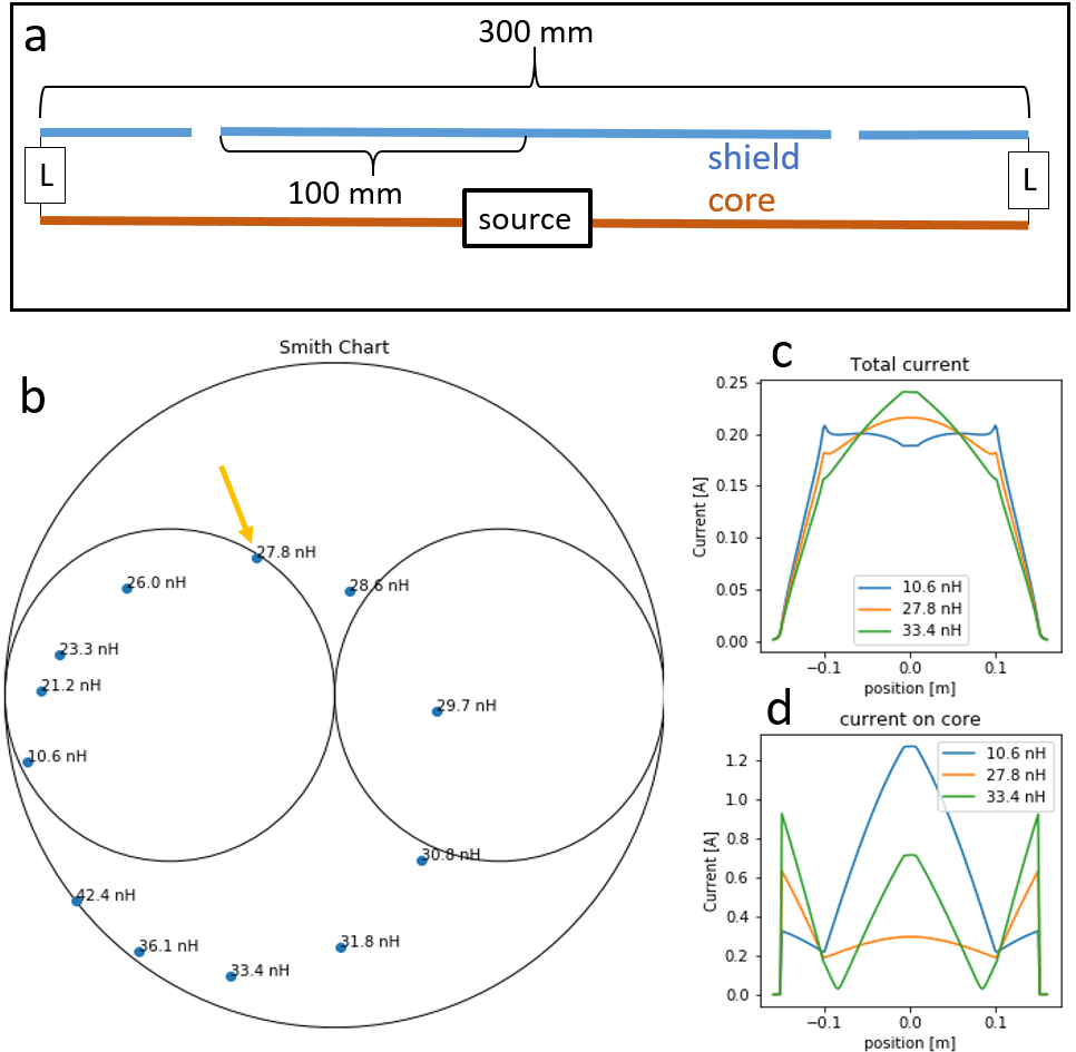
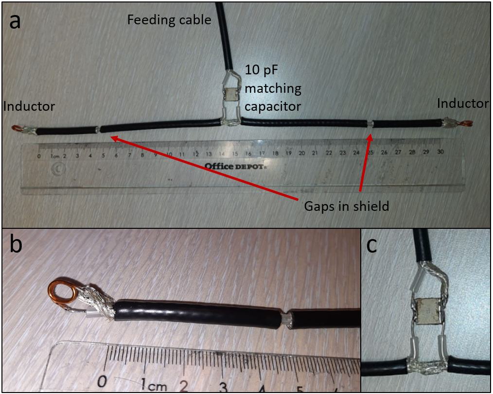
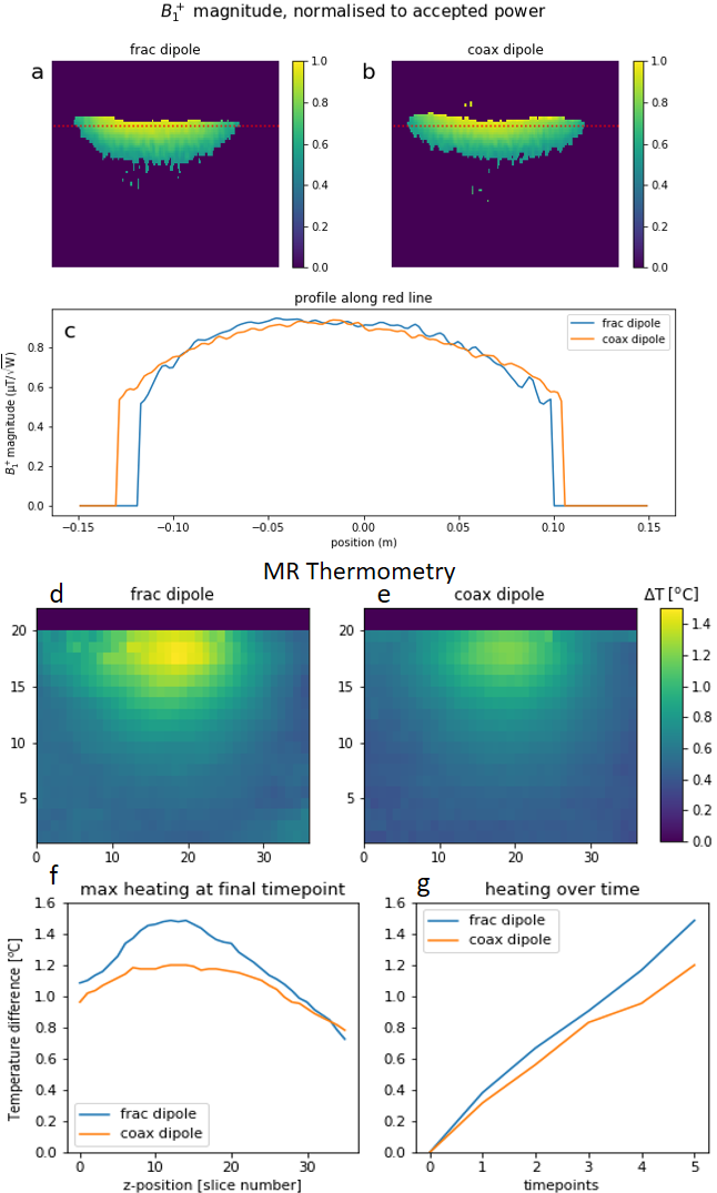
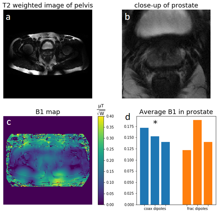
Figure 1b shows that placing the gaps further away from the center produces a flatter current distribution. Figures 1e,f show this results in a lower maximum electric field, and thus a better SAR efficiency. However, this also results in strong currents on the core (figure 1c) causing considerable losses. Additionally, the antennas that produce the flattest current distribution (gaps at 100 and 125 mm) have a very low impedance, making them difficult and sensitive to match. To reduce losses associated with these strong core currents, an inductor is added to each end of the antenna (figure 2a) connecting the shield to the core. For an antenna with gaps at 100mm from the center, an inductance value around 28 nH strongly reduces the core currents (figure 2d) while it also yields a beneficial input impedance which can be matched using a single parallel capacitor (figure 2b) and the antenna still has a relatively flat current distribution (figure 2c). Figure 3 shows photographs of the constructed “coax dipole antenna”.Figures 4a,b,c show the coax dipole antenna produces roughly the same B1 amplitude as the fractionated dipole antenna. However, as can be seen in figures 4d,e, the coax dipole causes approximately 18% less peak heating. Figure 5 shows in-vivo results obtained with an array of eight coax dipole antennas. Over three subjects, the maximum B1 value in the prostate was 13.7 µT, with 6.36 kW of arrived forward power. The coax dipole antennas were able to achieve similar B1 levels to the fractionated dipoles: on average 0.155 (coax) vs 0.150 (fractionated) µT/√W. The strongest nearest-neighbor coupling measured was -12 dB, with values below -15 dB being typical.
Discussion
Plain coax cable dipoles with appropriately placed gaps are able to achieve a flat current distribution. However, these gaps induce strong reflections to the power waves on the coax cable resulting in a strong standing wave on the central conductor with large losses. Adding inductors to the end of the antenna, in combination with the small piece of coax cable between the inductor and the gap effectively ‘matches’ the impedance transition at the gap. It reduces reflections and therefore core current amplitude and losses. In addition, it brings the impedance of the antenna to a point where it can be matched using a single parallel capacitor, all while maintaining a flat current distribution. For the antenna with gaps at 125mm, no lumped element value was found that satisfied these three criteria (flat current distribution, low core current and favorable input impedance). The coax dipole antenna achieves similar B1 values as the fractionated dipole antennas. A single coax dipole on a homogeneous phantom generates lower SAR than a fractionated dipole antenna. Future studies will focus on determining whether this increased SAR efficiency can also be demonstrated in-vivo and combining the antennas with flexible receiver coils. Note that due to its flexibility the coax dipole antenna can easily adjust to the curvature of the body while, remarkably, maintaining matched conditions.Conclusion
The coax dipole: a novel, flexible, low SAR dipole antenna for 7 Tesla is presented. On a homogeneous phantom, it reduces peak SAR by 18% while generating equal B1 as the current state-of-the-art. An array of eight coax dipoles produced on average 0.155 µT/√W (normalized to forward power) in the prostate of 3 volunteers.Acknowledgements
This project has received funding from the European Union's Horizon 2020 research and innovation programme under grant agreement No 736937.References
1. Raaijmakers AJE, Ipek O, Klomp DWJ, et al. Design of a radiative surface coil array element at 7 T: The single-side adapted dipole antenna. Magn Reson Med. 2011;66(5):1488-1497.
2. Raaijmakers AJE, Italiaander M, Voogt IJ, et al. The fractionated dipole antenna: A new antenna for body imaging at 7 Tesla. Magn Reson Med. 2016;75(3):1366-1374. doi:10.1002/mrm.25596
3. Avdievich NI, Solomakha G, Ruhm L, Bause J, Scheffler K, Henning A. Bent folded-end dipole head array for ultrahigh-field MRI turns “dielectric resonance” from an enemy to a friend. Magn Reson Med. 2020. doi:10.1002/mrm.28336
4. Connell IRO, Menon RS. Shape Optimization of an Electric Dipole Array for 7 Tesla Neuroimaging. IEEE Trans Med Imaging. 2019;PP(c):1-1. doi:10.1109/tmi.2019.2906507
5. Steensma B, van de Moortele PF, Ertürk A, et al. Introduction of the snake antenna array: Geometry optimization of a sinusoidal dipole antenna for 10.5T body imaging with lower peak SAR. Magn Reson Med. 2020. doi:10.1002/mrm.28297
6. Sadeghi-Tarakameh A, Torrado-Carvajal A, Ariyurek C, et al. Optimizing the Topography of Transmit Coils for SAR Management. Proc 26th Annu Meet ISMRM, Paris, Fr. 2018;0297.
7. Sadeghi-Tarakameh A, Jungst S, Wu X, et al. A New Coil Element for Highly-Dense Transmit Arrays : An Introduction to Non-Uniform Dielectric Substrate (NODES) Antenna. In: Proceedings of the 27th Annual Meeting of ISMRM, Montreal, Canada. ; 2019:0732.
8. Zivkovic I, Castro CA, Webb A. Design and characterization of an eight‐element passively fed meander‐dipole array with improved specific absorption rate efficiency for 7 T body imaging. NMR Biomed. 2019;(March):e4106. doi:10.1002/nbm.4106
9. Solomakha G, Leeuwen C van, Raaijmakers A, et al. The dual-mode dipole: A new array element for 7T body imaging with reduced SAR. Magn Reson Med. 2019;81(2):1459-1469. doi:10.1002/mrm.27485
10. Hurshkainen AA, Steensma B, Glybovski SB, et al. A parametric study of radiative dipole body array coil for 7 Tesla MRI. Photonics Nanostructures - Fundam Appl. 2020. doi:10.1016/j.photonics.2019.100764
11. Zhang B, Sodickson DK, Cloos MA. A high-impedance detector-array glove for magnetic resonance imaging of the hand. Nat Biomed Eng. 2018. doi:10.1038/s41551-018-0233-y
12. Ruytenberg T, Webb A, Zivkovic I. Shielded-coaxial-cable coils as receive and transceive array elements for 7T human MRI. Magn Reson Med. 2020. doi:10.1002/mrm.27964
13. Mollaei MSM, Van Leeuwen CC, Raaijmakers AJE, Simovski CR. Analysis of High Impedance Coils Both in Transmission and Reception Regimes. IEEE Access. 2020. doi:10.1109/ACCESS.2020.3009367
14. Erturk MA, Lagore RL, Adriany G, Metzger GJ. A 16-channel Combined Shielded-Loop-Resonator and Dipole Transceiver Array Design for Body Imaging at 7.0 Tesla. In: Proc. Intl. Soc. Mag. Reson. Med. 28 Sydney. ; 2020:4263.
15. Ianniello C, de Zwart JA, Duan Q, et al. Synthesized tissue-equivalent dielectric phantoms using salt and polyvinylpyrrolidone solutions. Magn Reson Med. 2018;80(1):413-419. doi:10.1002/mrm.27005
16. Nehrke, K. and Börnert, P. (2012), DREAM—a novel approach for robust, ultrafast, multislice B1 mapping. Magn Reson Med, 68: 1517-1526. https://doi.org/10.1002/mrm.24158
17. Rieke V, Pauly KB. MR thermometry. J Magn Reson Imaging. 2008. doi:10.1002/jmri.21265
18. Yarnykh VL. Actual flip-angle imaging in the pulsed steady state: A method for rapid three-dimensional mapping of the transmitted radiofrequency field. Magn Reson Med. 2007;57(1):192-200. doi:10.1002/mrm.21120
Figures