1022
An Electromagnetic Actuator for Brain Magnetic Resonance Elastography1the Institute for Medical Imaging Technology, Shanghai Jiao Tong University, Shanghai, China, 2the Department of Radiology, Ruijin Hospital, Shanghai, China
Synopsis
Effective actuators are crucial for brain magnetic resonance elastography (MRE). In this study, we designed, tested, and verified an electromagnetic actuator. With a grappler-shaped design, the actuator was easy to use and comfortable to wear on head. Phantom and brain experiments indicated that the proposed actuator did not interference with routine imaging sequences. It generated stable shear waves with a full width at half maximum of 0.3 Hz in the frequency spectrum. Phantom and brain MRE demonstrated that the actuator could carry out multi-frequency MRE with a high frequency accuracy.
Introduction
Magnetic resonance elastography (MRE) is one of the few non-invasive methods that can measure the brain tissue in vivo. 1 Different from the clinical application of MRE in liver tissue measurement, shear waves must be effectively transmitted through the skull. 2,3 Therefore, an effective actuator for brain MRE is desired.Current clinically used actuator is pneumatically driven, but studies have shown that it might produce extra peaks in the frequency spectrum. 4 The mechanical actuator can generate accurate frequency but may produce extra noise due to an external motor. 4,5 Electromagnetic actuator, like the piezo-electric actuator, is convenient to control, and the actuation frequency can be accurately tuned. 6 However, the challenge of using an electromagnetic actuator is the electromagnetic compatibility. 6 In addition, a specific design for convenient usage in clinical settings is also crucial. 7
In this study, we proposed an electromagnetic actuator for brain MRE. A grappler design was used to transmit waves to the whole brain. The performances of the actuation in terms of frequency accuracy, electromagnetic compatibility, and wave generation were evaluated.
Methods
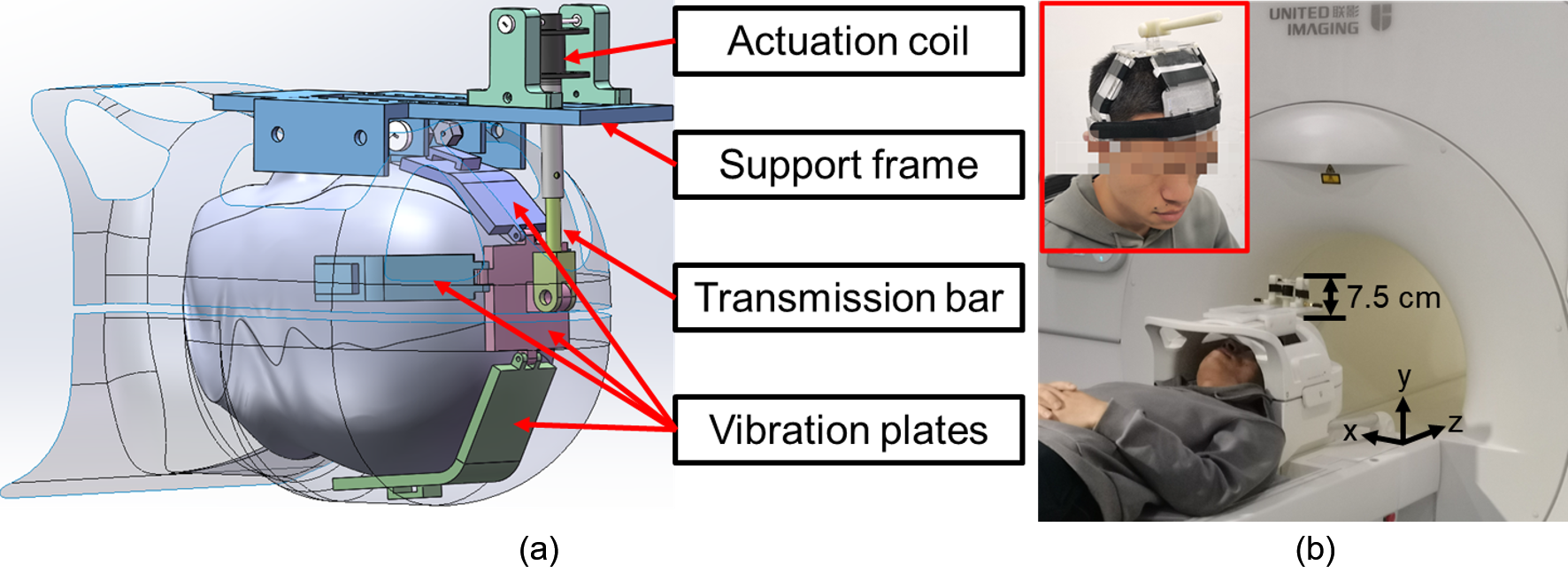
With a splint-like structure, a support frame holds the actuation coil in place on the top of the MR head coil (Figure 1a). A transmission bar is designed to connect the actuation coil to 5 vibration plates, transmitting the vibration from the actuation coil to the plates. A curved design is adopted for all vibration plates for better fitting of the head. Soft elastic bandages could be used to wrap around the vibration plates to ensure that the plates hold the whole brain firmly. The components that stand outside of the head coil have a height of 7.5 cm (Figure 1b). Therefore, the whole actuator could fit into the MR bore easily.We evaluated the performance of frequency actuation of the proposed actuator and compared it with that of a pneumatic actuator. Vibrations of the actuator during MRE were recorded using an accelerometer with a gradient echo (GRE) based MRE sequence and an echo planar imaging (EPI) based MRE sequence. A 3T MRI scanner (uMR 790, United Imaging Healthcare, Shanghai, China) was used for the experiment and all following imaging.
To estimate the magnetic field produced by the actuation coil more precisely, finite element simulations were carried out using COMSOL. In addition, to evaluate the overall influence of the metal components, we tested the electromagnetic compatibility by measuring the signal-to-noise (SNR) ratio of a spherical liquid phantom with a T1 weighted (T1W) and T2 weighted (T1W) clinical sequence, respectively.
A 1:1 human skull model was manufactured to evaluate the performance of the actuator. The brain tissue was simulated by filling the skull with glycerol gelatin 8 and three cylindrical agar phantoms with different concentrations as inclusions. In addition, three healthy volunteers were also recruited for MRE imaging. A 2D GRE based MRE sequence was used for image acquisition. After phase unwrapping and filtering, shear modulus map was estimated using a local frequency estimation (LFE) method. 9
Results and discussion
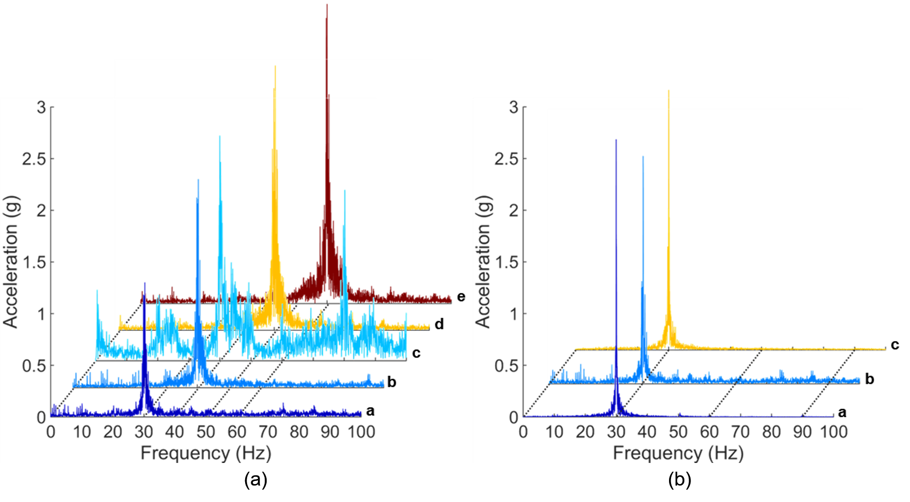
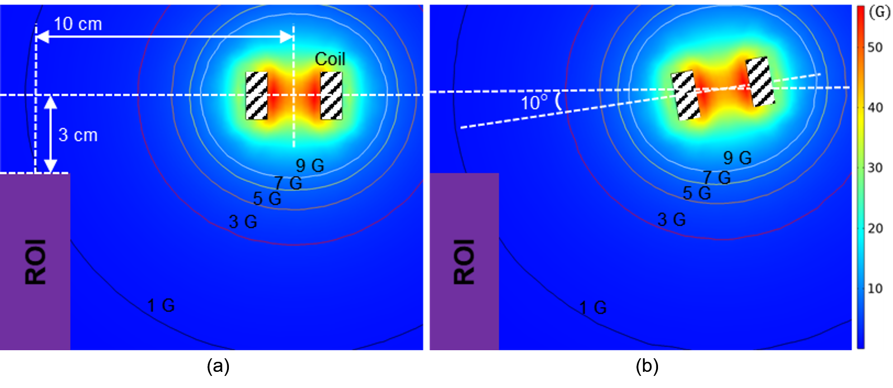
The frequency spectra showed the full width at half maximum (FWHM) value of each measured frequency was ~1 Hz for both actuators (Figure 2a). Compared with the spectrum of the pneumatic actuator, we observed no significant off-center frequency component for the electromagnetic actuator. In addition, the FWHM of the vibration frequency was ~0.3 Hz with few off-central frequency peaks when without applying any imaging sequence (Figure 2b). Compared with the GRE-based MRE sequence, the FWHM of the EPI-based MRE sequence was smaller and less background noise was also observed.The simulated magnetic flux density showed that the ROI of the MRE imaging was outside the 3-G contour (Figure 3), which was less than one part in 10000 compared with the 3-T field. Therefore, the interference of the fringe field produced by the actuator was at a paltry level.
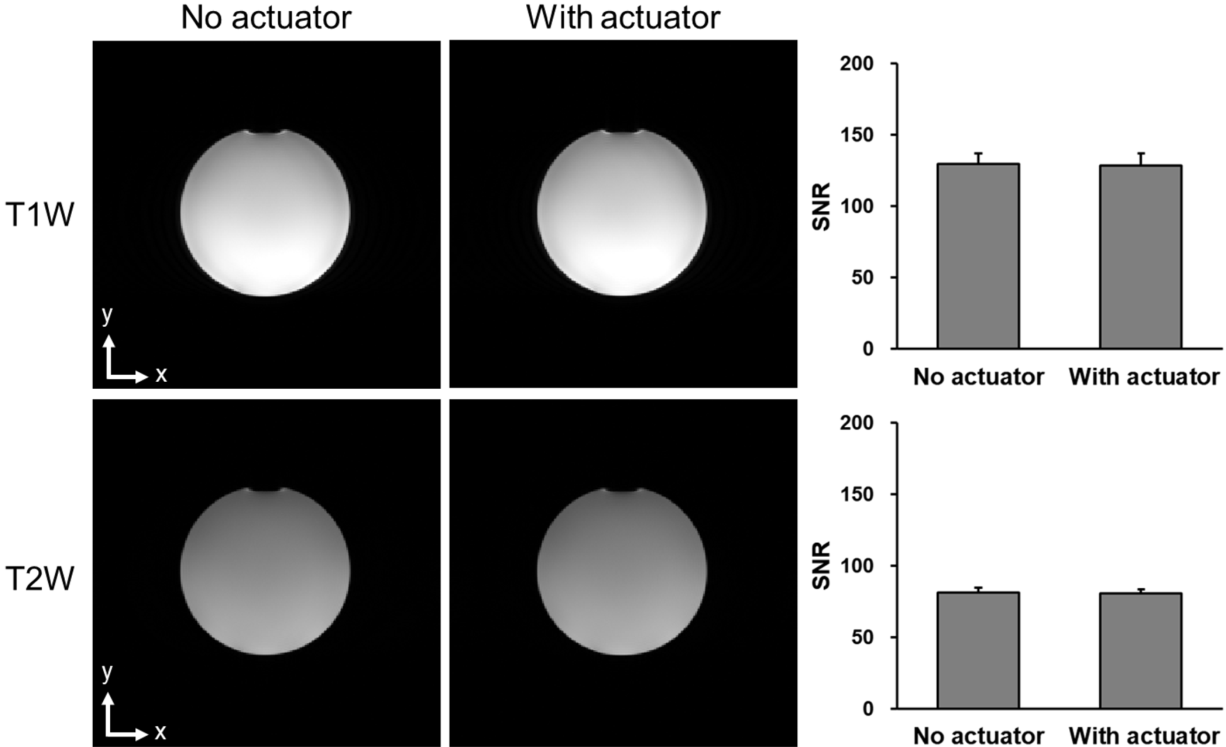
Images of the SNR test showed no observable difference in both T1W and T2W images (Figure 4). Analysis of the SNR values from 6 different slices from each set of images showed no significant differences. This indicated that the proposed actuator did not interfere with the imaging.
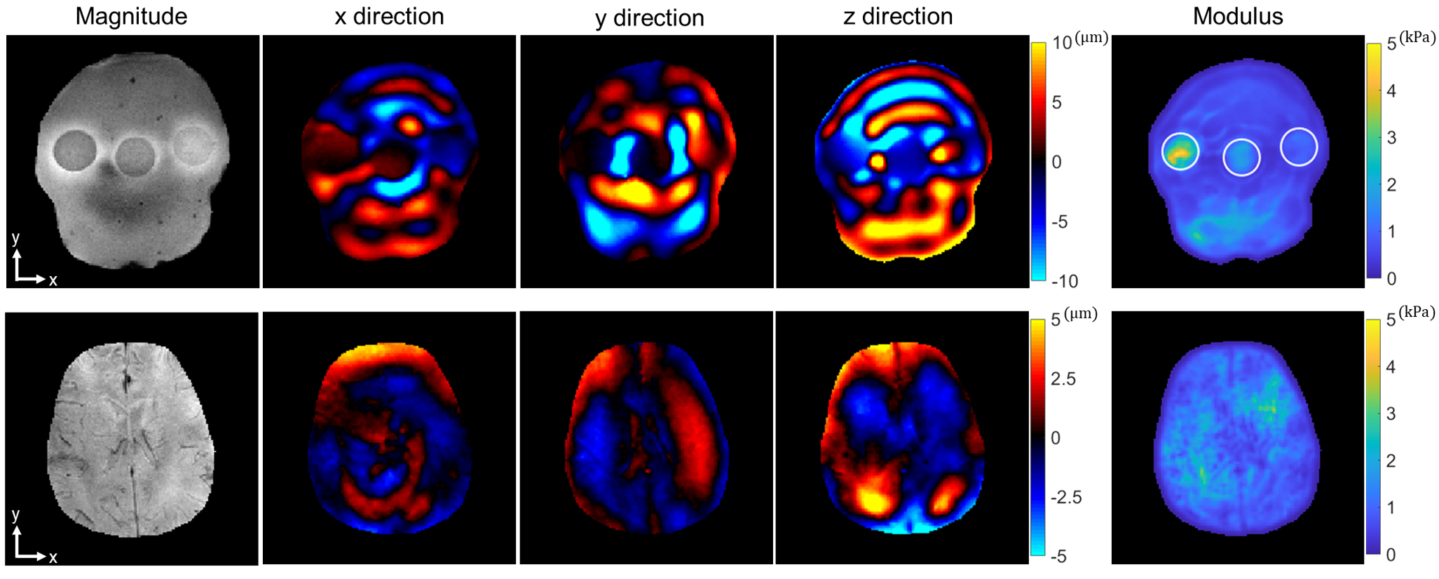
For the phantom and volunteer imaging, the real part of the first harmonic of the displacement components in three encoding directions at 30 Hz were shown in Figure 5. The calculated elastogram showed a clear distinguishing stiffness map between the three agar inclusions. Clear wave patterns could be observed in three directions within the brain.
Conclusion
In this study, we proposed an electromagnetic actuator for brain MRE. The vibration was transmitted into the brain via a grappler-shaped design. Simulation, phantom, and human experiment results showed the proposed actuator could carry out MRE measurements with multiple frequencies and high frequency accuracy. Future studies include using the actuator in a couple of clinical investigations.Acknowledgements
Funding support from grant 31870941 from National Natural Science Foundation of China (NSFC) and grant 1944190700 from Shanghai Science and Technology Committee (STCSM) are acknowledged.References
1. Murphy MC, Huston J, 3rd, Ehman RL. MR elastography of the brain and its application in neurological diseases. Neuroimage. 2019;187:176-183.
2. Sack I, Beierbach B, Hamhaber U, Klatt D, Braun J. Non-invasive measurement of brain viscoelasticity using magnetic resonance elastography. NMR Biomed. 2008;21(3):265-271.
3. Castera L, Forns X, Alberti A. Non-invasive evaluation of liver fibrosis using transient elastography. J Hepatol. 2008;48(5):835-847.
4. Runge JH, Hoelzl SH, Sudakova J, et al. A novel magnetic resonance elastography transducer concept based on a rotational eccentric mass: preliminary experiences with the gravitational transducer. Phys Med Biol. 2019;64(4):045007.
5. Hirsch S, Guo J, Reiter R, et al. MR elastography of the liver and the spleen using a piezoelectric driver, single-shot wave-field acquisition, and multifrequency dual parameter reconstruction. Magn Reson Med. 2014;71(1):267-277.
6. Uffmann K, Ladd ME. Actuation systems for MR elastography: design and applications. IEEE Eng Med Biol Mag. 2008;27(3):28-34.
7. Tse ZT, Janssen H, Hamed A, Ristic M, Young I, Lamperth M. Magnetic resonance elastography hardware design: a survey. Proc Inst Mech Eng H. 2009;223(4):497-514.
8. Feng Y, Zhu M, Qiu S, et al. A multi-purpose electromagnetic actuator for magnetic resonance elastography. Magn Reson Imaging. 2018;51:29-34.
9. Fovargue D, Nordsletten D, Sinkus R. Stiffness reconstruction methods for MR elastography. NMR Biomed. 2018;31(10):e3935.
Figures