0857
Improvements in in vivo imaging and temperature mapping using passive “propeller-beanie” antenna in transcranial MR-guided focused ultrasound1Vanderbilt University Institute of Imaging Science, Nashville, TN, United States, 2Department of Radiology and Radiological Sciences, Vanderbilt University Medical Center, Nashville, TN, United States, 3Department of Biomedical Engineering, University of Virginia, Charlottesville, VA, United States, 4Department of Biomedical Engineering, Vanderbilt University, Nashville, TN, United States
Synopsis
Transcranial MR-guided focused ultrasound (tcMRgFUS) neurosurgery is a non-invasive treatment for essential tremor and many emerging applications. In FDA-approved Insightec tcMRgFUS system, however, RF reflections create curved dark bands in brain images. In this work, we reported the first B1+ and temperature maps in a healthy volunteer with passive crossed wires to alleviate B1+ dark bands and inhomogeneity in a tcMRgFUS system. Consistent with simulation results and previous experimental results in phantoms, the “propeller-beanie” antenna can significantly alleviate dark band artifacts in Insightec tcMRgFUS system, which improves temperature precision and may enable the use of diffusion imaging to monitor treatment.
Purpose:
Transcranial MR-guided focused ultrasound (tcMRgFUS) neurosurgery is a non-invasive treatment for essential tremor and many emerging applications [1-3]. In the FDA-approved Insightec tcMRgFUS system, however, RF reflections from the conductive transducer surface create curved dark bands in brain images that run through midbrain locations targeted for essential tremor. Previous work demonstrated that dark band artifacts can be well alleviated using a pair of “propeller-beanie” passive wire antennas in a head-shaped phantom [4], or using a wire screen [5]. In this study, we report the first in vivo results, without and with the presence of passive wires, and quantify improvements in RF transmit field strength and temperature precision.Methods:
Passive wires and holder fabrication:A series of passive wires with length between 9 and 13 cm were investigated using ANSYS Electronic Desktop (HFSS 19.2, Designer, ANSYS Inc., Canonsburg, PA). Based on the simulation results, a 3D-printed holder was made to attach to the top of a swim cap and hold a pair of 11 cm 26-gauge wires (Figure 1A). The two wires were perpendicular to each other and placed crossed each other at the center. Then the swim cap was attached to the head of a healthy volunteer, with wires lifted up approximately 1 cm above the head by the holder (Figure 1B). In practice, to be compatible with FUS the wires will be suspended from a plastic structure that will run along the inside surface of the transducer, instead of the swim cap.
Experiments:
MR imaging experiments were performed on the Insightec ExAblate Neuro 4000 system (Insightec Ltd, Tirat Carmel, IL) installed at a GE Discovery MR750T 3T scanner (GE Healthcare, Waukesha, WI). A healthy human volunteer was scanned with and without wearing the wires, with approval from the Institutional Review Board at the University of Virginia. The default FUS multi-gradient-recalled echo temperature mapping scan was used to acquire 35 time-series images (TE 3.3, 8.1, 12.8, 17.6, and 22.4 ms, TR 51.7 ms, 28 cm FOV, 30 degrees flip (nominal), slice thickness 3 mm, 128 x 256 matrix, 280 Hz per pixel) for use in calculating temperature precision with and without the wires. Three-plane B1+ maps were also acquired with and without the wires using the Bloch–Siegert method [6].
Results and Discussions:
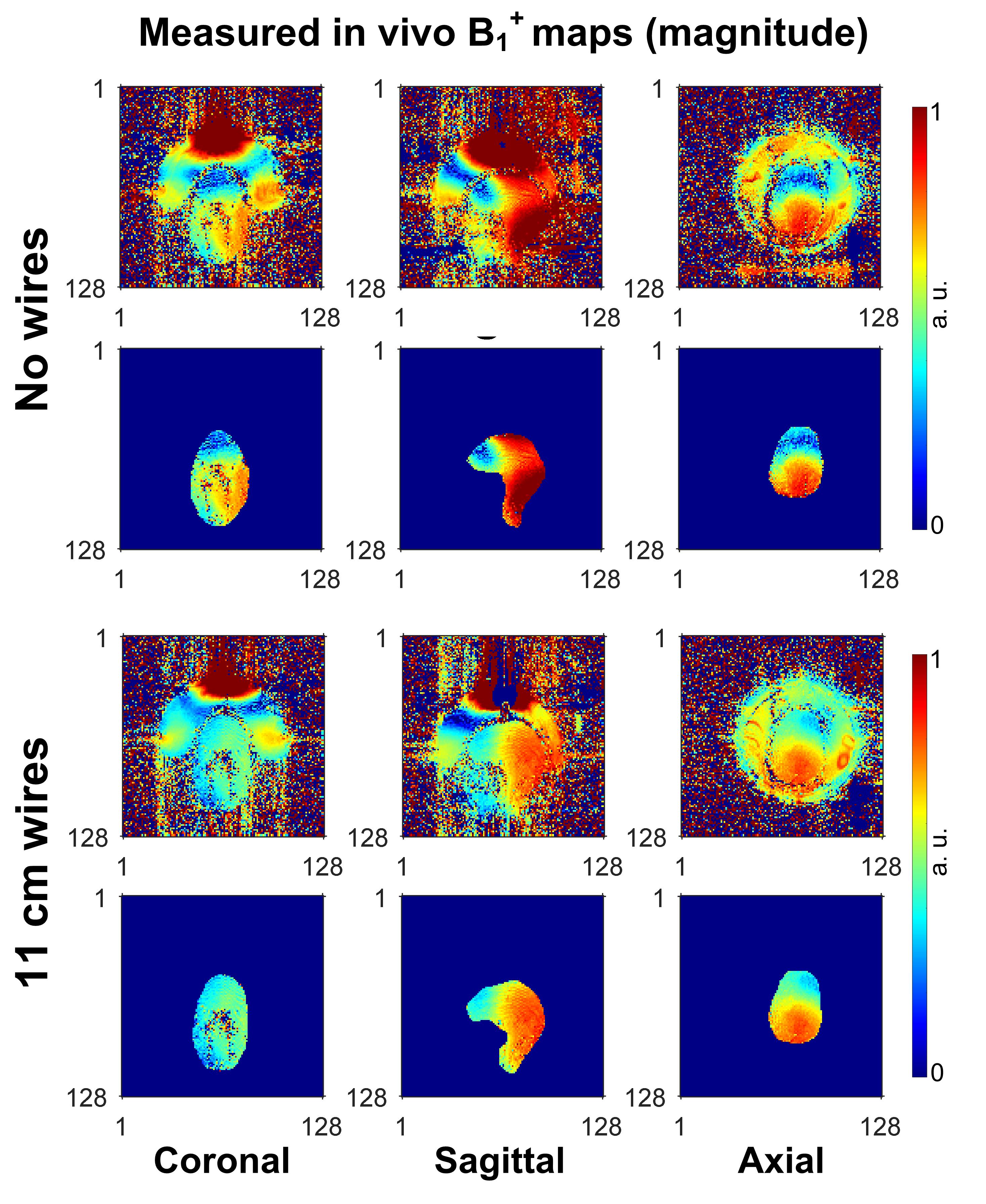
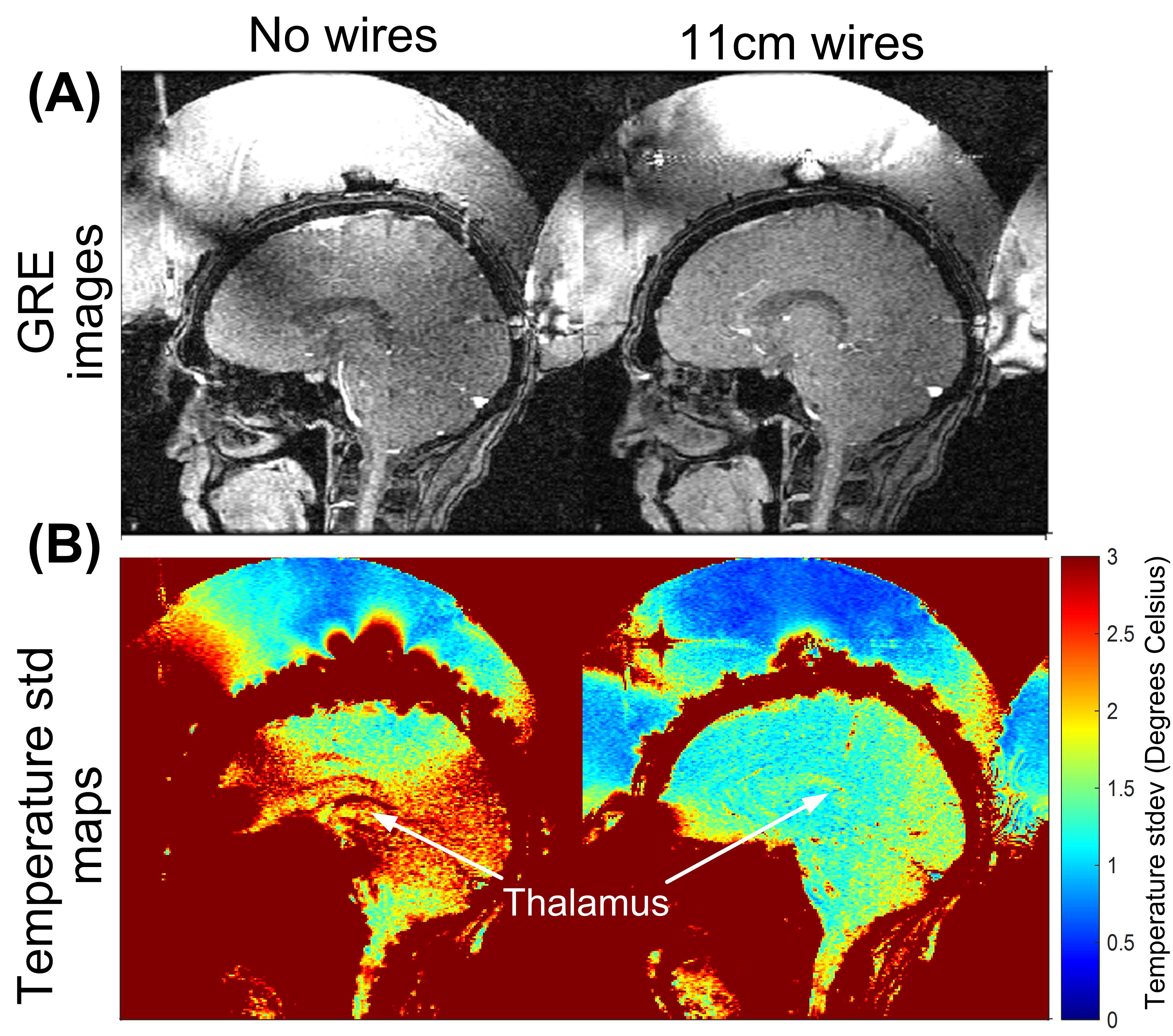
Figure 2 shows the simulated transmit RF transmit fields with wire lengths between 9 and 13 cm. The 11 cm-long wires recover the most RF field in the dark band area and achieve the best B1+ uniformity overall. This length was therefore used in the in vivo scans. Figure 3 shows the normalized B1+ maps without and with wires in three planes. Consistent with the simulation results, the B1+ uniformity was significantly improved using the 11-cm-long wires, with coefficients of variation (CoV) improved from 32%/30%/38% to 22%/20%/23% in the coronal/sagittal/axial planes. Figure 4 shows the first echo time image (TE = 3.3 ms) from the temperature mapping scan and through-time temperature standard deviation maps in the sagittal plane. The accuracy of temperature mapping was significantly improved with the wires, especially through the dark band (spatiotemporal temperature standard deviation 6.12 degrees Celsius (without wires) vs. 3.17 Celsius (with wires)).Conclusion:
In this work, we reported the first B1+ and temperature maps in a healthy volunteer with passive crossed wires to alleviate B1+ dark bands and inhomogeneity in a transcranial MR-guided FUS system. Consistent with simulation results and previous experimental results in phantoms, the “propeller-beanie” antenna method can significantly alleviate the dark band artifacts in Insightec tcMRgFUS system, which improves temperature precision and may enable the use of diffusion imaging to monitor treatment. We note that the human head position highly deviates from the usually roughly central position due to the lack of a stereotactic frame which is used in actual treatments. This may have led to less uniform wire B1+ maps compared to the simulation. However, even in this suboptimal case a marked improvement was found.Acknowledgements
This work was supported by NIH R21 EB029639.References
1. Focused Ultrasound Foundation. Brain Program’s mini-workshop called “a landmark example” of academic–industrial collaboration. Aug 2012. https://www.fusfoundation.org/Newsletter-Articles/brainprograms-mini-workshop-called-a-landmark-example-of-academic-industrial-collaboration
2. McDannold, N., 2005. Quantitative MRI-based temperature mapping based on the proton resonant frequency shift: review of validation studies. International journal of hyperthermia, 21(6), pp.533-546.
3. McDannold, N., Clement, G.T., Black, P., Jolesz, F. and Hynynen, K., 2010. Transcranial magnetic resonance imaging–guided focused ultrasound surgery of brain tumors: initial findings in 3 patients. Neurosurgery, 66(2), pp.323-332.
4. Yan, X., Allen, S., Grissom, W.A., “Propeller Beanie” Passive Antennas to Alleviate Dark Bands in Transcranial MR-Guided Focused Ultrasound. In Annual Proceedings Meeting of the International Society of Magnetic Resonance in Medicine, 2020. p103.
5. Hadley, J.R., Odeen, H., Merrill, R., Haag-Roeger, R.C., Rieke, V., Payne, A., and Parker, D.L., 2019. Improving image quality in transcranial magnetic resonance guided focused ultrasound using a copper screen. In proceedings of the 19th ISTU, Barcelona.
6. L. I. Sacolick, F. Wiesinger, I. Hancu, and M. W. Vogel. B1 mapping by Bloch-Siegert shift. Magn Reson Med, 63(5):1315–1322, 2010.
Figures
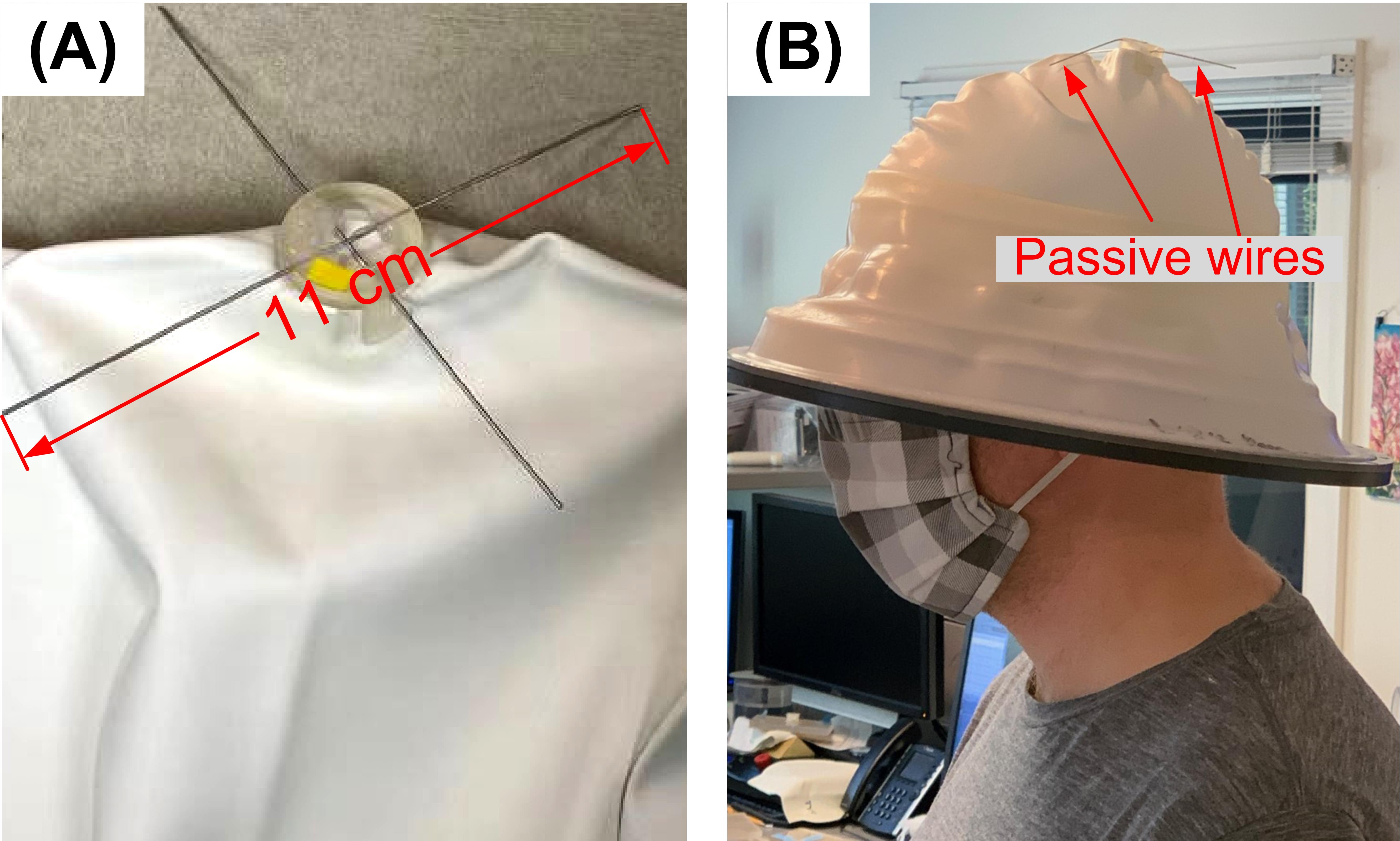
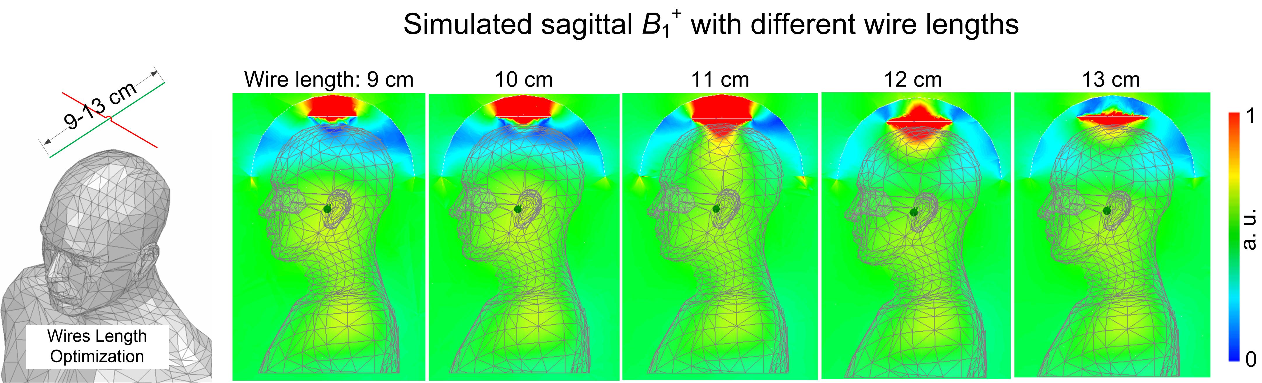
Figure 2 Optimization setup to evaluate the best length for the passive wires (left) and the simulated RF transmit magnitude (|B1+|) maps. The optimal wire length was 11 cm (highest B1+ efficiency near the middle of the brain) which was used for the in vivo experiments.