0855
Minimal Artifact Actively Shimmed Metallic Needles for Interventional MRI1Department of Radiology, Vanderbilt University Institute of Imaging Science, Nashville, TN, United States, 2Department of Radiology, Vanderbilt University Medical Center, Nashville, TN, United States, 3Department of Mechanical Engineering, University of Arkansas, Fayetteville, AR, United States
Synopsis
Artifacts caused by large magnetic susceptibility differences between metallic probes and the surrounding tissue are a persistent problem in many interventional MRI applications. In previous work, we presented the concept, design and modeling of active shims for metallic needles. In this work, we present the experimental demonstration of recovery of metallic probe induced signal loss at 3 Tesla. Effective recovery of lost signal and correction of field inhomogeneity is shown across needle orientations and imaging sequences.
INTRODUCTION
Signal voids caused by metallic needles pose significant visualization, guidance and monitoring challenges in many interventional MRI (iMRI) applications including biopsies1-3, ablations4,5 and brachytherapy6,7. In earlier work, we presented the design and simulation of active shims for metallic probes and demonstrated correction of the ΔB0 and reduction of the signal void around a titanium needle8. In this work, we present the actual fabrication and correction of the signal void artifact around a titanium needle at 3T. Artifact correction is shown to extend across imaging with multiple contrasts and orientations.METHODS
SimulationsThe needle induced field, shim coil paths, shim fields and field shimming were simulated in Matlab. ΔB0 around a 4/3 mm OD/ID, hollow Titanium needle with a 30o single-sided bevel (Volume Susceptibility: 𝟀 = 182*10-6 )9 in Water (𝟀 = -9.05*10-6 )9 was modeled at 3T using Fourier-analysis field modeling10. A set of 18 orthogonal 2-coil shim paths were modeled for fields produced and shimming8,11, from which a pair consisting of a ½ turn loop angled at the bevel angle (CN90) and a split wire loop (CN0) was selected for best predicted performance (Figure 1).
Needle and Shim Insert Fabrication
A 4/3 mm OD/ID, 15 cm hollow titanium tube was used to fabricate the needle. For mounting the shim coils, a 2.5 mm, 15 cm former with a bevel and orthogonal wire slots was designed in Solidworks (Dassault Systemes, USA) (Figure 2a). The insert was 3D printed on a ProJet 3500 printer (3D Systems Inc, USA). 26-gauge enameled copper wire was placed into the slots by hand and insulated using a single layer of kapton tape. The insert was then slid inside the needle with the bevels aligned with each other (Figure 2b).
The needle was tightened into a central bore hole of a 3D printed holder with a compartment for shim wire connections (Figure 2c). Shim wires were connected to 20 feet long twisted cables for current supply (E3631A, Keysight Technologies, USA, 6V/±5A, 25V//±1A). A pair of high impedance 127 MHz RF chokes12 were placed in line along each current path to minimize RF pulse induced currents.
Shimming Experiments
All experiments were performed on a Philips 3 Tesla scanner with a 2-channel body RF transmit and 16 channel neuro-vascular receive coil. Two 15 cm diameter cylindrical phantoms with domes that allowed needle insertions at different angles were designed and 3D printed (Figure 2d). The objectives of the needle shimming experiment were to a) demonstrate and quantify the recovery of lost signal around the needle at different orientations and b) show artifact reduction in different imaging sequences commonly used in iMRI applications.
The currents necessary to shim the needle at four different orientations were simulated: i) 0,0,0 ii) 90,0,0 iii) 0,18,30 and iv) 20, -30,0 degrees. The needle containing the shim coils was then inserted into the water phantom through the guide holes in these orientations and imaging was performed with 3D GRE with fieldmapping, 3D FSE, 2D single slice balanced SSFP and single slice multishot EPI sequences for each (Parameters in Figure 3). Images were acquired in the planes parallel and perpendicular (for 3D GRE) to the needle bevel. For each orientation, images were acquired without and with the pre-calculated shim currents supplied to the two coils simultaneously.
Shim Performance Evaluation
Shim performance was assessed by estimating the volume of the signal void around the needle for the GRE images. Voxels with less than 25% of the mean signal from a reference slice away from the needle were identified as the signal void and the total volume of these voxels in mm3 was calculated. The percentage of lost signal recovered by shimming was also calculated.
RESULTS
Simulations predicted the need for a) 1.17A, 0 A b) 0A, -1.15A c) 0.97A, 0 A and d) 0.819A, -0.29A in the CN0 and CN90 coils for the four needle orientations. Figure 4 shows parallel, orthogonal and cross-section slices from the 3D GRE acquisitions. Significant recovery of the lost signal around the needle is evident in all orientations with shimming. The volume of the signal void reduced from 8097, 8047, 3324 and 5072 mm3 without shimming to 2510, 2816, 1428, 1995 mm3 with shimming respectively for the four orientations. This represented recovery of 69.0%, 64.9%, 57.1% and 60.6% of the lost signal. This value would in-fact be higher if the volume of the needle could be exactly estimated and accounted for. The fieldmaps show the correction of the underlying ΔB0. Without shimming, there is significant field wrapping around the needle due to extremely high ΔB0, which is eliminated with shimming. Figure 5 shows Balanced SSFP, TSE and Multishot EPI images without and with shimming. Recovery of signal is seen to be consistent across different contrasts due to the correction of the underlying ΔB0.DISCUSSION
Significant recovery of lost signal around a metallic needle extending across orientations and imaging contrasts is shown with active shimming with pre-calculated shim values. Minimal artifact needles can find many uses in iMRI including for improving target visibility in biopsies, monitoring of therapy in ablations, delineation of targets and at risk structures in brachytherapy among others.Acknowledgements
This work was supported by NIBIB R21EB025258. I would like to thank Dr William A Grissom, Gary Drake and Dr Megan Poorman help and for advice on field modeling and 3D printing.References
1. Weiss CR, Nour SG, Lewin JS. MR-guided biopsy: a review of current techniques and applications. J Magn Reson Imaging. 2008 Feb;27(2):311-25. PMID: 18219685 doi: 10.1002/jmri.21270.
2. Nour SG, Lewin JS Percutaneous biopsy from blinded to MR guided: an update on current techniques and applications. Magn Reson Imaging Clin N Am. 2005 Aug;13(3):441-64. PMID: 16084412 DOI: 10.1016/j.mric.2005.04.009
3. Butts K, Pauly JM, Daniel BL, Kee S, Norbash AM.Management of biopsy needle artifacts: techniques for RF-refocused MRI. J Magn Reson Imaging. 1999 Apr;9(4):586-95. PMID: 10232519
4. Xinyang Liu, Kemal Tuncali, William M. Wells, Gary P. Zientara. Automatic probe artifact detection in MRI-guided cryoablation. Conference: Proc. SPIE 8671, Medical Imaging 2013: Image-Guided Procedures, Robotic Interventions, and Modeling, 86712E DOI: 10.1117/12.2008530
5. Clasen S, Pereira PL. Magnetic resonance guidance for radiofrequency ablation of liver tumors. J Magn Reson Imaging. 2008;27(2):421-33. doi: 10.1002/jmri.21264.. PMID: 18219677 DOI: 10.1002/jmri.21264
6. Wachowicz K, Thomas SD, Fallone BG. Characterization of the susceptibility artifact around a prostate brachytherapy seed in MRI. Med Phys. 2006;33(12):4459-67. PMID: 17278797 DOI: 10.1118/1.2364052
7. Frank SJ, Stafford RJ, Bankson JA, Li C, Swanson DA, Kudchadker RJ, Martirosyan KS. A novel MRI marker for prostate brachytherapy. Int J Radiat Oncol Biol Phys. 2008 ;71(1):5-8. PMID: 18406882 DOI: 10.1016/j.ijrobp.2008.01.028
8. Sengupta S. Modeling of active shimming of metallic needles for interventional MRI. Magn Reson Med. 2020 Nov;84(5):2858-2870. doi: 10.1002/mrm.28320. Epub 2020 Jun 29. PMID: 32597521; PMCID: PMC7396316.
9. Schenck JF. The role of magnetic susceptibility in magnetic resonance imaging: MRI magnetic compatibility of the first and second kinds. Med Phys. 1996 ;23(6):815-50
10. Salomir, R., de Senneville, B. D. and Moonen, C. T. A fast calculation method for magnetic field inhomogeneity due to an arbitrary distribution of bulk susceptibility. Concepts Magn. Reson, 2003, 19B: 26–34. doi:10.1002/cmr.b.10083
11. Masullo A. https://www.mathworks.com/matlabcentral /fileexchange/42237-biot-savart-direct-integration-on-a-generic-curve
12. Xia J, Sappo CR, Grissom WA, and Yan X Low-profile AC/DC coils without RF Chokes , In Proceedings of the 28th Annual Meeting of ISMRM, Toronto, Canada, 2020, pp 1276.
Figures
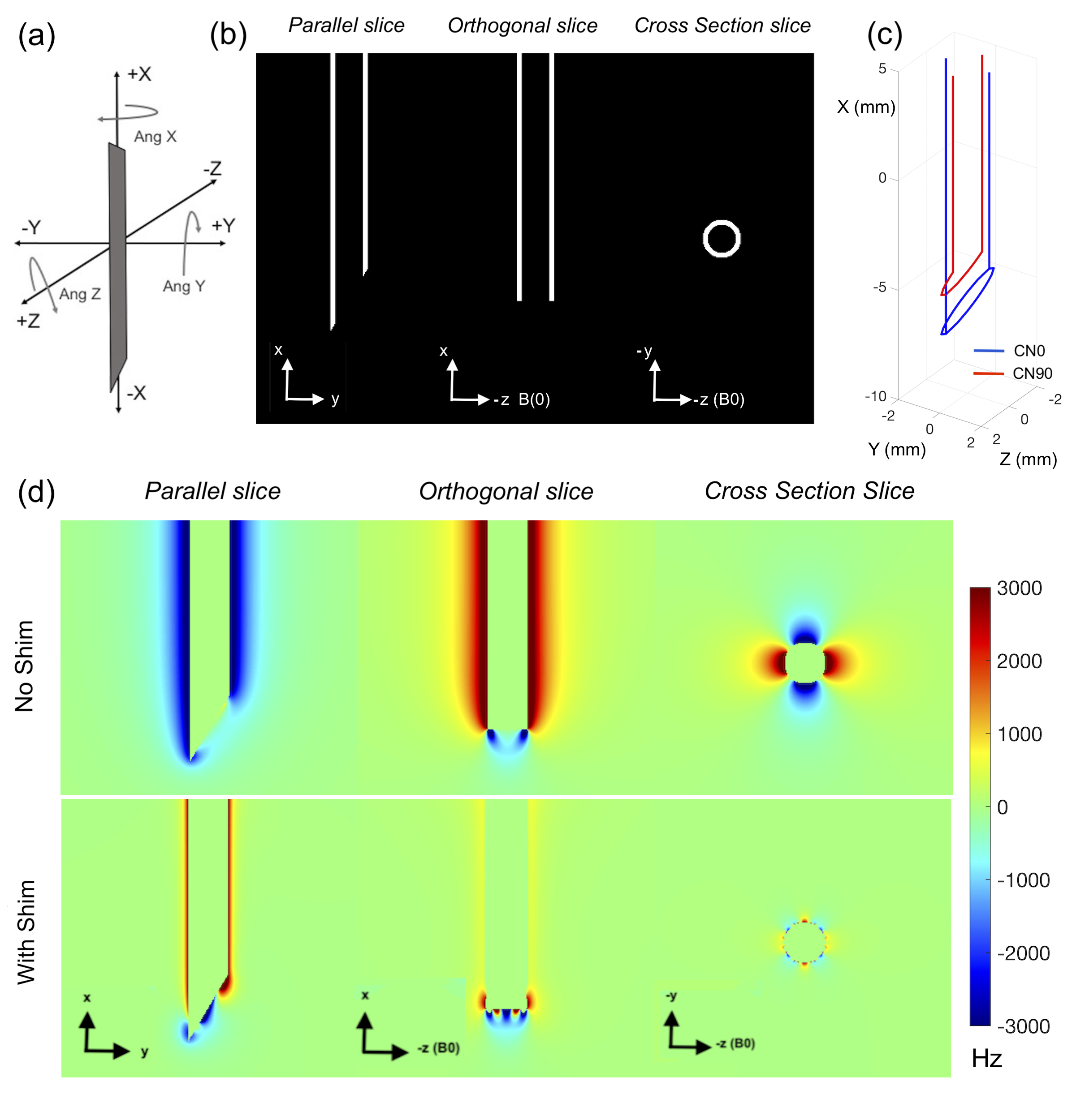
Figure 1
Modeling of active shimming of the 4 mm/3 mm OD/ID Titanium needle (a) Definition of needle angulations with the needle in the 0,0,0 position in the magnet frame of reference b) Titanium needle setup in Matlab for field modeling. White voxels represent metal and black voxels represent water (c) Selected 2 coil shim paths. CN90 (red) is a ½ turn angled loop and CN0 (blue) is a split tip double wire loop (d) Simulated parallel, orthogonal and cross-section fieldmaps without and with shimming with 1.17 A in CN0 and 0 A in CN90.
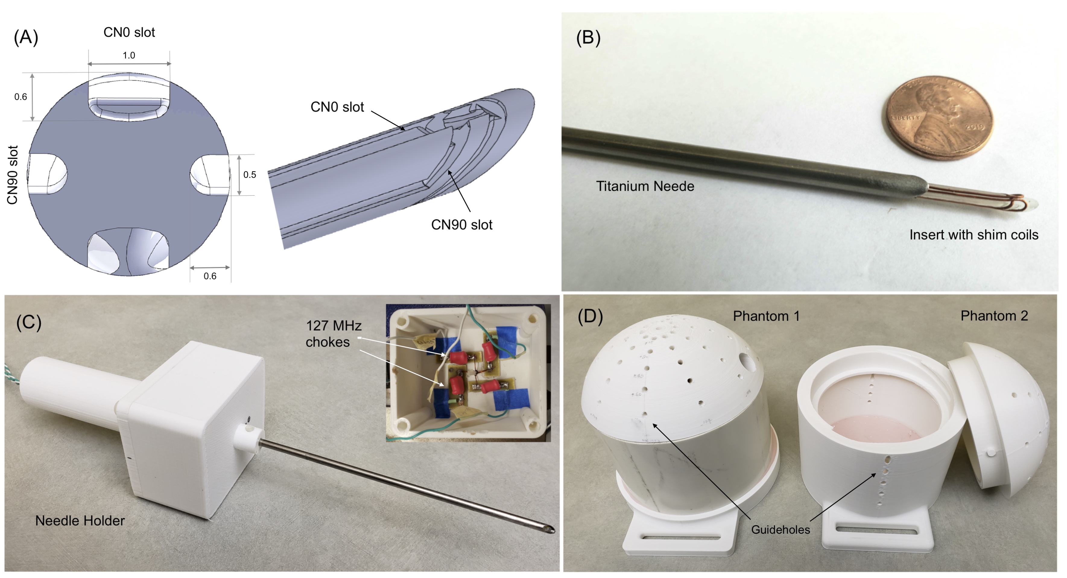
Figure 2
Active shimming hardware (a) Shim insert design with bevel and orthogonal slots for shim wires (b) Shim insert inside the titanium needle (c) Needle placed in holder with compartment for electronics (d) Phantoms with guide holes at different angles used for experiments.
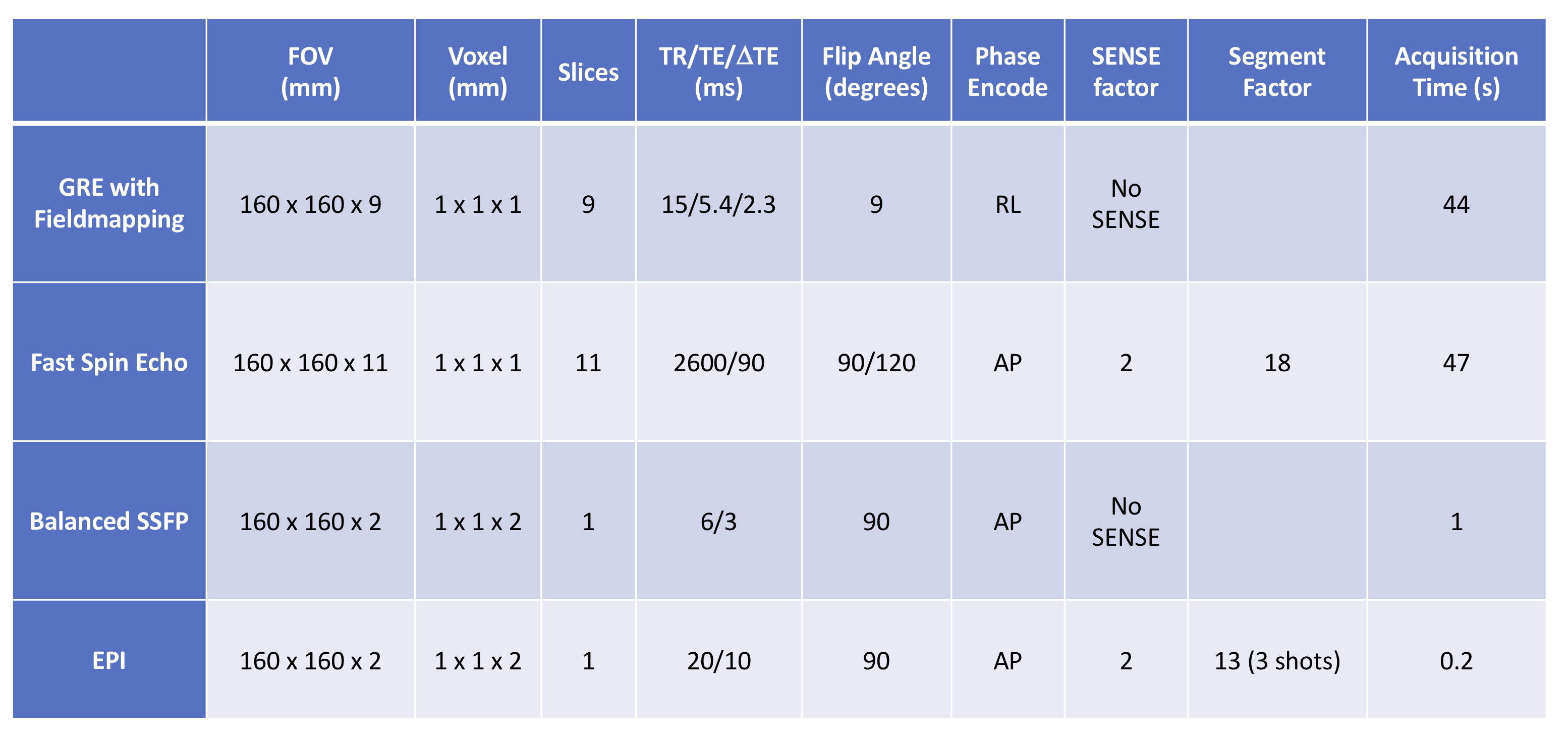
Figure 3
Parameters used for imaging experiments.
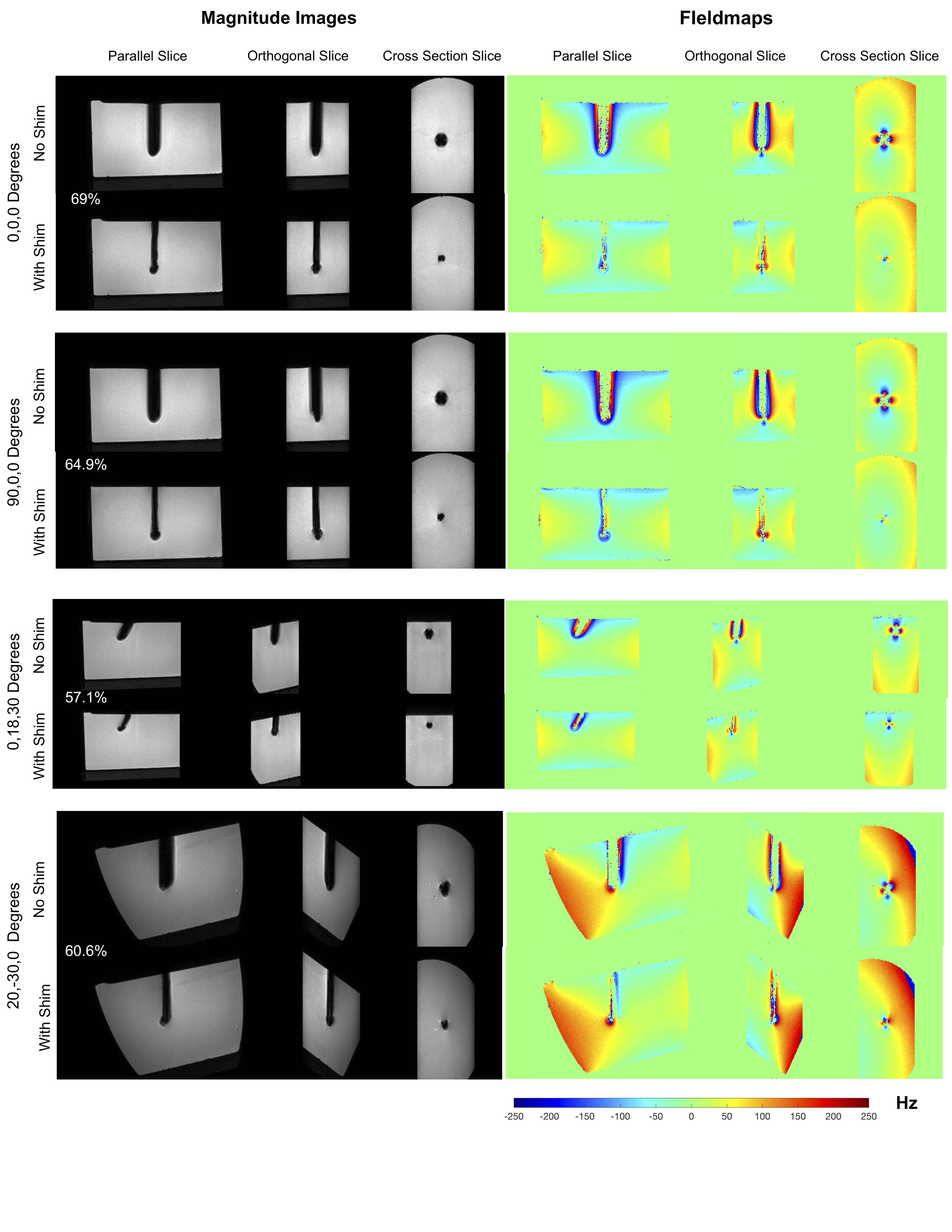
Figure 4
Results of active shimming, 1 x 1 x 1 mm3 3D GRE images and fieldmaps. Excellent recovery of lost signal is achieved in all orientations using pre-estimated shim currents. The width of the signal void approaches the needle width in all cases. Fieldmaps show correction of the underlying ΔB0. Note that the regions closest to the rod with field information in the ‘With Shim’ case have no corresponding field information in the ‘No Shim’ case due to signal loss. The percentage of signal recovered (not accounting for the needle itself) is indicated for all orientations.
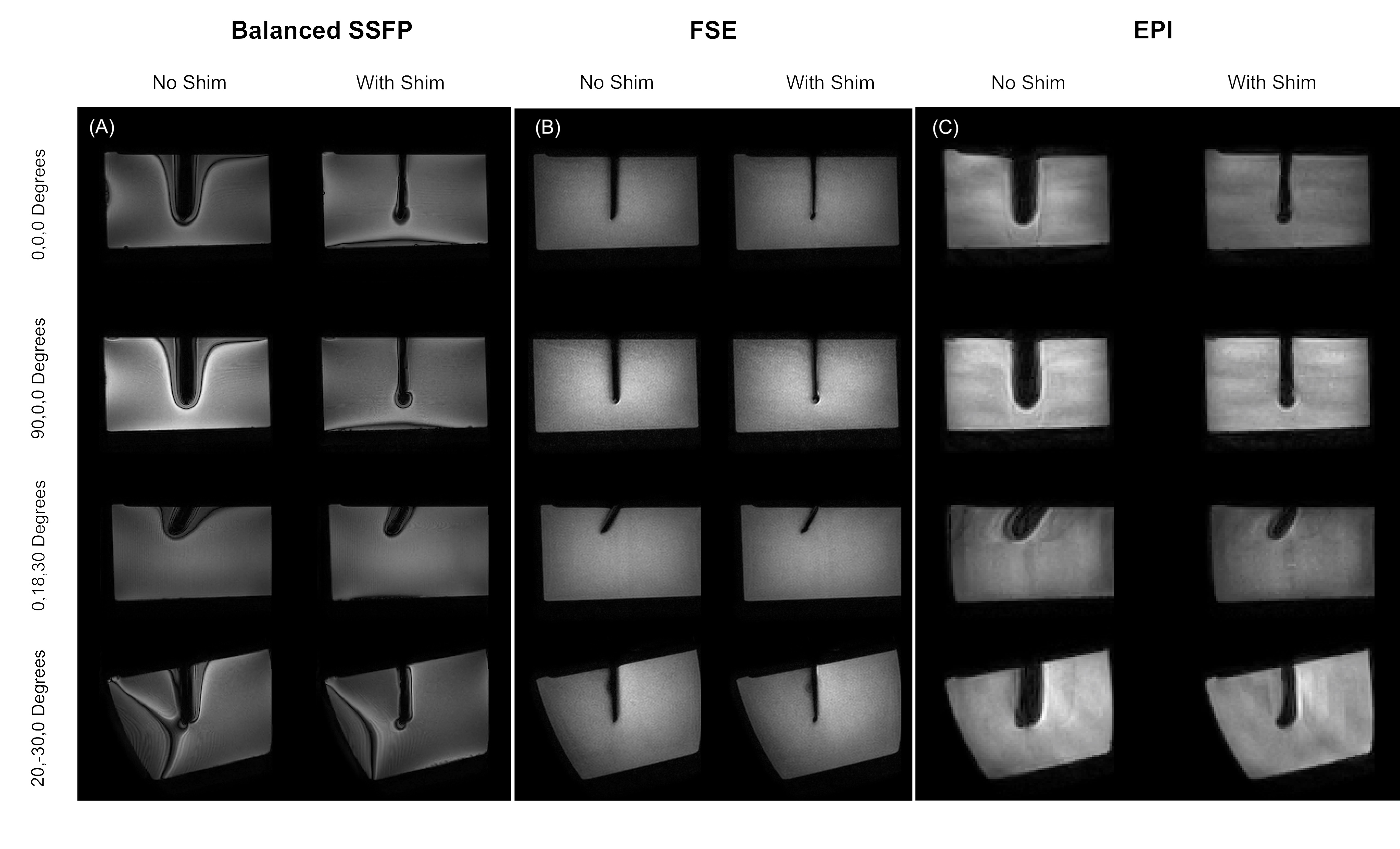
Figure 5
Results of active shimming in 1 x 1 x 2 mm3 Balanced SSFP, 1 x 1 x 1 mm3 FSE and 1 x 1 x 2 mm3 3 shot EPI images. Recovery of lost signal is achieved in all sequences and all orientations. Balanced SSFP images show reduced off-resonance related banding. FSE images approach the true width of the 4 mm needle with shimming.