0786
Uniform Magnetization Transfer contrast at 7T with Direct Saturation Control1Biomedical Engineering and Imaging Sciences, King's College London, London, United Kingdom, 2MR Research Collaborations, Siemens Healthcare Limited, Frimley, United Kingdom, 3Siemens Healthcare GmbH, Erlangen, Germany, 4Centre for the Developing Brain, King's College London, London, United Kingdom
Synopsis
Conventional RF pulse design methods optimize for rotation of the magnetization. However, in systems with Magnetization Transfer (MT) with a semisolid pool, the dynamics do not follow the Bloch equations; saturation of the semisolid depends on |B1+|2, making it particularly sensitive to B1+ inhomogeneities. This work employs a novel pulse design framework termed ‘Direct Saturation Control’ (DSatC) to directly consider semisolid saturation. We use this to design composite pulses with spatially uniform semisolid saturation using parallel transmition at 7T, where B1+ is intrinsically highly inhomogeneous. In-vivo results show much more homogeneous MT contrast when using DSatC.
Introduction
Parallel transmission (pTx) is used to mitigate $$$B_1^+$$$ inhomogeneity at 7T, by controlling the $$$B_1^+$$$ field via a linear superposition of multiple transmit channels. Current pulse design methods make use of pTx by designing for a target flip angle1. While this makes sense for free-water magnetization, in systems with a significant semisolid pool the dynamics do not follow the Bloch equations. Crucially, the semisolid magnetization is considered to have such a short $$$T_2$$$ ($$$T_2^s\approx{}10\mu{}s$$$) that it can be modeled by a longitudinal component alone. There are two important consequences for semisolid magnetization: (i) the concept of ‘flip angle’ is not valid; (ii) it is not affected by applied gradients in-between RF pulses. In this work we employ a novel pTx pulse design method called Direct Saturation Control2 (DSatC) that directly controls the spatial distribution of $$$\left|B_1^+\right|^2$$$ to obtain uniform in-vivo magnetization transfer (MT) contrast.Theory
The dynamics of MT systems are described by the binary spin-bath3 model that comprises free-water magnetization $$$M^f$$$ and semisolid magnetization $$$M^s$$$:$$\frac{d}{dt}\begin{bmatrix}M_x^f\\M_y^f\\M_z^f\\M_z^s\end{bmatrix}=\begin{bmatrix}0&\gamma{}\mathrm{\textbf{G}}\cdot{}\mathrm{\textbf{r}}&-\gamma{}B_{1,y}&0\\-\gamma{}\mathrm{\textbf{G}}\cdot{}\mathrm{\textbf{r}}&0&\gamma{}B_{1,x}&0\\\gamma{}B_{1,y}&-\gamma{}B_{1,x}&0&0\\0&0&0&-W\end{bmatrix}\begin{bmatrix}M_x^f\\M_y^f\\M_z^f\\M_z^s\end{bmatrix}\quad{}[1]$$
$$W=\pi{}\gamma^2{}\left|B_1^+\right|^2g\left(T_2^s,\Delta\right)\quad{}[2]$$
Here, relaxation and exchange effects are excluded since they occur typically over much longer time-scales than the short RF pulse durations employed in pulsed MT4. While $$$M^f$$$ is rotated by the applied $$$B_1^+$$$ field, $$$M_z^s$$$ is saturated at rate $$$W$$$ depending on $$$\left|B_1^+\right|^2$$$ and absorption lineshape $$$g\left(T_2^s,\Delta\right)$$$ at the frequency-offset $$$\Delta$$$ of the RF pulse. Hence, the time-averaged spatial distribution of $$$\left|B_1^+\right|^2$$$ determines the semisolid saturation5:
$$\langle{}B_1^2(\mathbf{\mathrm{x}})\rangle{}=\frac{1}{TR}\int_0^{TR}\left|B_1^+\left(\mathrm{\textbf{x}},t\right)\right|^2dt\quad{}[3]$$
For a pTx system with $$$N_{ch}$$$ channels,
$$\left|B_1^+\left(\mathrm{\textbf{x}},t\right)\right|^2=\left|\sum_{j=1}^{N_{ch}}s_j\left(\mathrm{\textbf{x}}\right)b_j\left(t\right)\right|^2\quad{}[4]$$
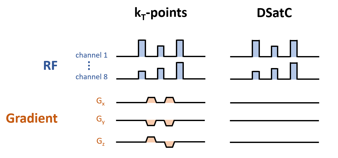
where $$$s_j(\mathrm{\textbf{x}})$$$ is the transmit sensitivity and $$$b_j$$$ the RF waveform in the $$$j^{th}$$$ channel. In this work we consider a series of $$$N_{sp}$$$ identical sub-pulses $$$b$$$ weighted by different complex factors $$$w$$$; essentially the same structure as a 3D kT-points6 (Figure 1) pulse:
$$\langle{}B_1^2(\mathbf{\mathrm{x}})\rangle{}=\sum_{i=1}^{N_{sp}}\left|\sum_{j=1}^{N_{ch}}s_j\left(\mathrm{\textbf{x}}\right)w_{ji}\right|^2\langle{}b^2\rangle{}\quad{}[5]$$
The pulse design problem is then defined as:
$$\begin{aligned}w_{ji}:=\underset{w_{ji}}{\arg}\min&||\langle{}B_1^2(\mathrm{\textbf{x}})\rangle{}-\mathrm{Target}||^2\quad{}[6]\\\quad{}\mathrm{s.t.}\,\,&\mathrm{SAR}(w_{ji})<20\mathrm{W}\cdot{}kg^{-1}\\\quad{}&\mathrm{hardware~constraints}\end{aligned}$$
where $$$\mathrm{Target}$$$ sets the desired spatial distribution of $$$\langle{}B_1^2(\mathrm{\textbf{x}})\rangle{}$$$.
Methods
Experiments were conducted on a 7T scanner (MAGNETOM Terra, Siemens Healthcare, Erlangen, Germany) in research configuration, with an 8-TX-channel head coil (Nova Medical, Wilmington MA, USA) using a prototype MT-weighted spoiled gradient-recalled-echo sequence (SPGR). In-vivo scanning of two healthy volunteers was performed in accordance with local ethics, obtaining Magnetization Transfer Ratio (MTR) images:$$MTR(\%)=100\times{}\frac{M_{ref}-M_{sat}}{M_{ref}}\quad{}[7]$$
where $$$M_{ref}$$$ is a reference SPGR image with no prep-pulse and $$$M_{sat}$$$ is a SPGR image acquired with a saturation prep-pulse designed with DSatC (eq.[6]) or in circular polarized (CP) mode. The excitation pulse was always performed in CP mode and using a low flip angle $$$\alpha_{exc}=3^\circ$$$ such that the MTR maps reflect predominantly the semisolid saturation. For all experiments $$$b$$$ was a Gaussian waveform applied at frequency-offset $$$\Delta=2\mathrm{kHz}$$$. $$$B_1^+$$$ mapping was done using a pre-saturation turbo-FLASH sequence7, prior to shim optimization. MTR maps were acquired using $$$N_{sp}=\{1,2,3\}$$$. Calculations were fully scanner-integrated within MATLAB (MathWorks, Natick, MA, USA) taking $$$\approx{}20sec$$$.
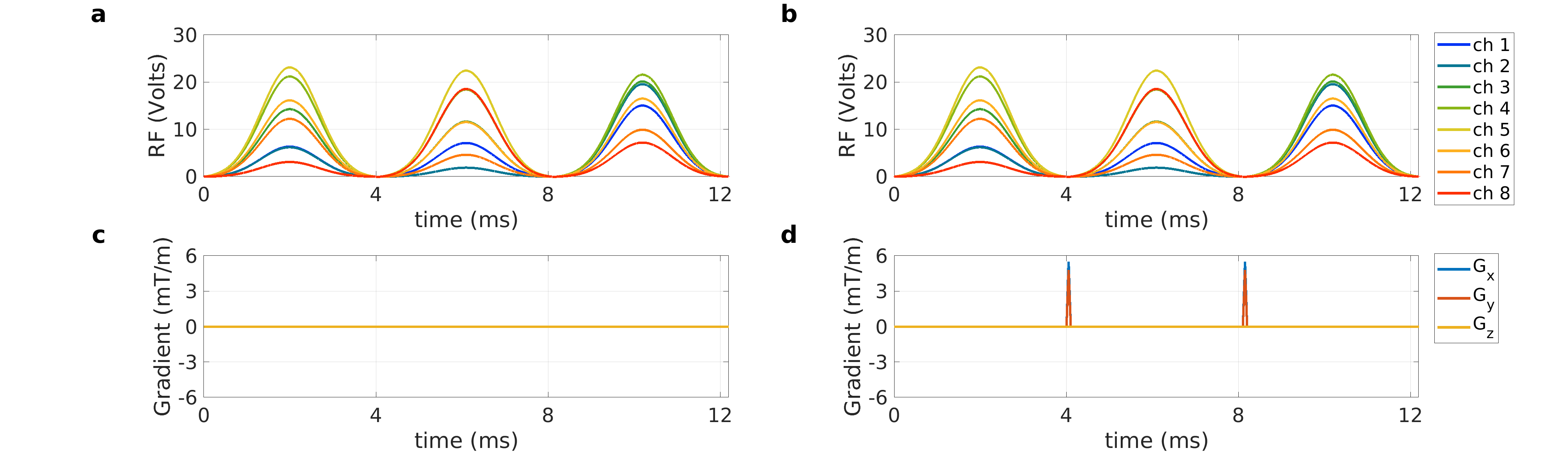
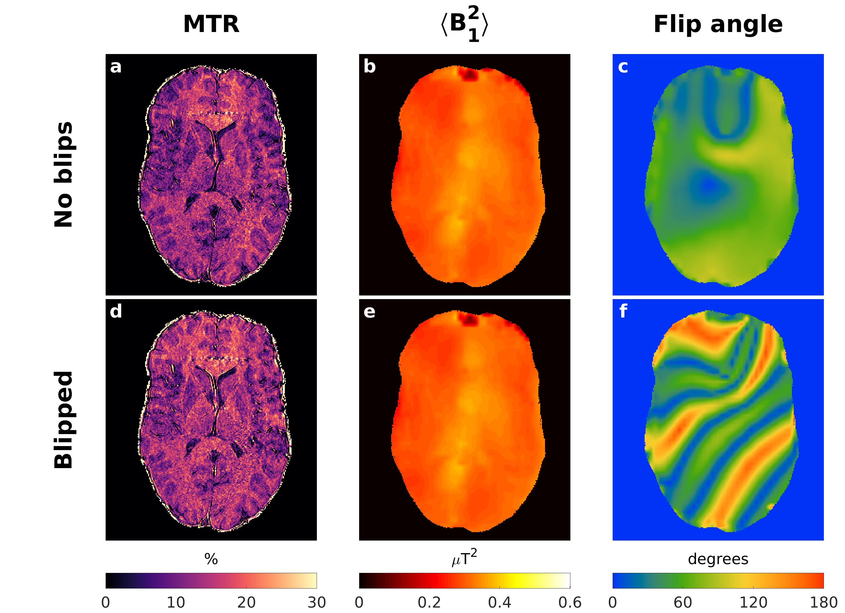
To demonstrate that gradient blips do not affect the MT contrast, DSatC using 3 sub-pulses was acquired twice – with and without gradients blips producing $$$4\pi$$$ phase roll across the x- and y-FOV between the sub-pulses.
Results
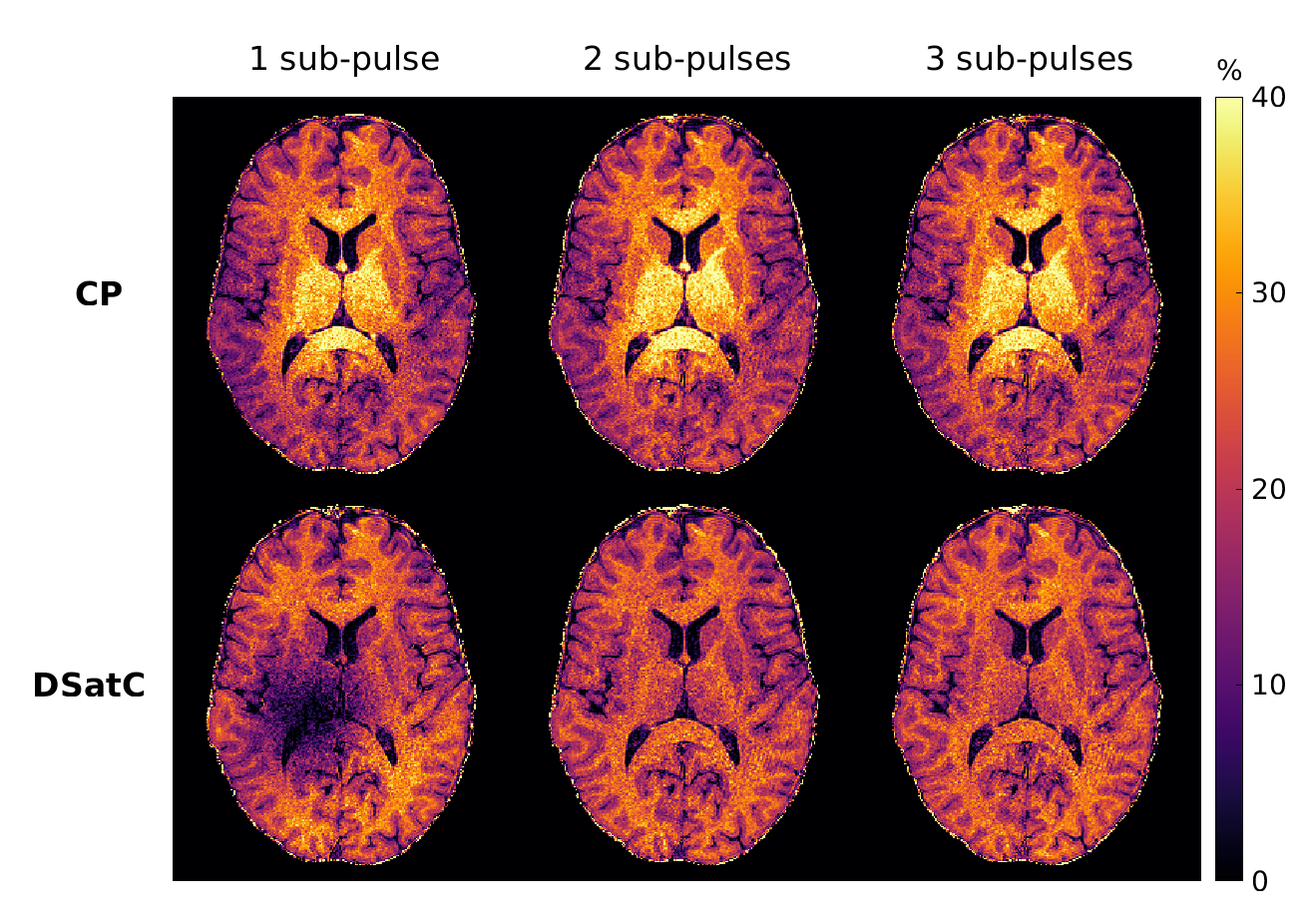
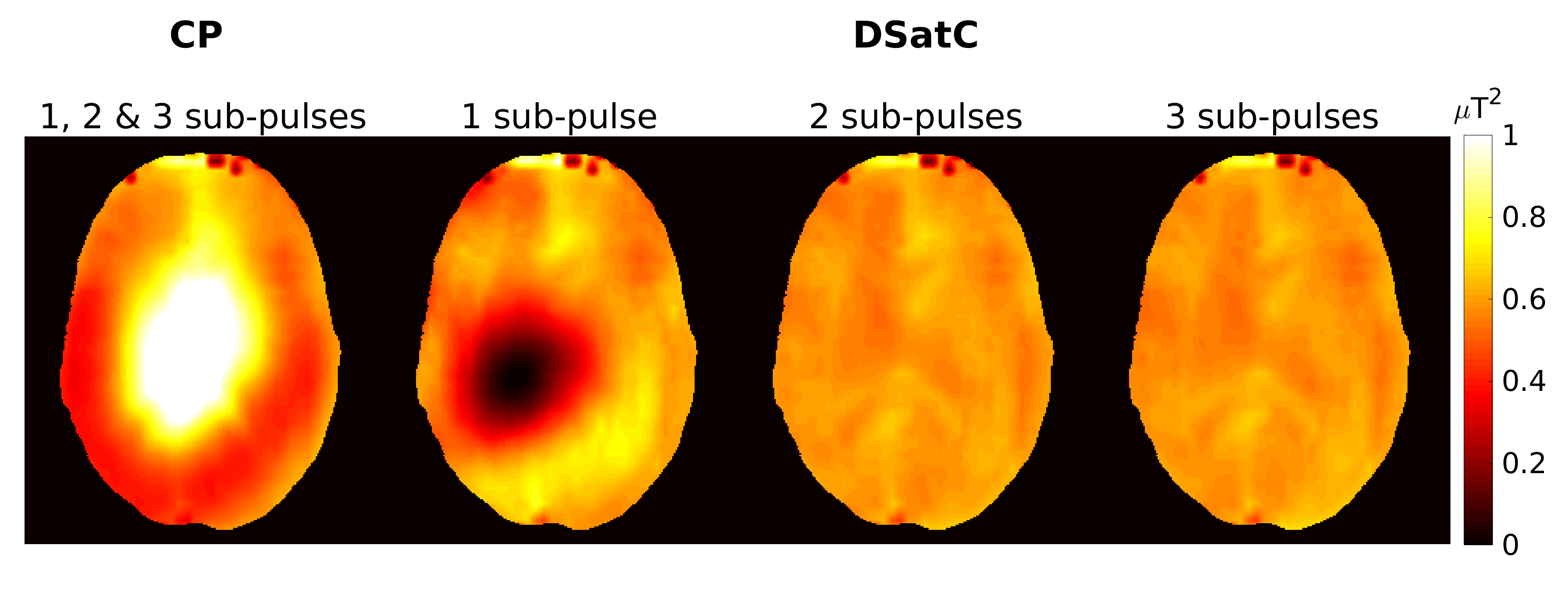
MTR maps acquired from one volunteer in Figure 2 show a significant improvement in the saturation homogeneity using DSatC with 2 and 3 sub-pulses. With CP the contrast is independent of the number of sub-pulses, whilst DSatC with 1 sub-pulse had a region with no saturation. The contrast observed correlates well with the respective $$$\langle{}B_1^2\rangle{}$$$ maps in Figure 3.Figure 5 shows the MTR, $$$\langle{}B_1^2\rangle{}$$$ and flip angle maps using the pulses in Figure 4 acquired from another volunteer, including the experiment with and without added gradient blips.
Discussion
In-vivo results showed considerably more uniform MT contrast with DSatC using more than 1 sub-pulse. The observed MT contrast agreed well with the predicted $$$\langle{}B_1^2\rangle{}$$$ of the saturation pulse, as expected from the binary spin-bath model. The proposed pulse design differs from other pTx pulse design methods as the semisolid pool saturates with $$$\left|B_1^+\right|^2$$$ and has no transverse magnetization. Previous work on ‘saturation’ pulses’8,9 considered saturation of free-water magnetization and therefore still employed gradients. For semisolid saturation gradients are not effective - this was experimentally verified by applying the same saturation prep-pulse twice - with and without gradient blips. Whilst blips radically change the projected “flip angle”, $$$\langle{}B_1^2\rangle{}$$$ stays constant, and the observed MTR maps showed virtually no difference. This observation supports the assertion that only $$$\langle{}B_1^2\rangle{}$$$ is important for semisolid saturation, underlining the need for the proposed design approach.The insensitivity to gradients is actually a limiting factor for how well we can control the spatial semisolid saturation, since gradients are a key additional degree-of-freedom used for ”flip angle” based optimization. One potential further avenue to explore is the use of gradients during RF activity which changes the frequency-offset $$$\Delta$$$, hence giving additional control over the saturation rate $$$W$$$ assuming the absorption lineshape is known.
Conclusion
This work demonstrated use of a pTx pulse design method called DSatC to homogenize the saturation of the semisolid pool in systems with MT. In-vivo results at 7T showed significant improvement despite intrinsic inhomogeneity of the RF fields. We also demonstrate that standard pulse design methods that optimize for flip angle are ineffective at solving this problem.Acknowledgements
This work was funded by the King’s College London & Imperial College London EPSRC Centre for Doctoral Training in Medical Imaging [EP/L015226/1] and supported by a Wellcome Trust Collaboration in Science Award [WT 201526/Z/16/Z] and the Wellcome/EPSRC Centre for Medical Engineering [WT 203148/Z/16/Z].References
1. Grissom W, Yip CY, Zhang Z, Stenger VA, Fessler JA, Noll DC. Spatial domain method for the design of RF pulses in multicoil parallel excitation. Magn. Reson. Med. 2006. 56:620–629 doi: 10.1002/mrm.20978.
2. Leitão D, Tomi-Tricot R, Liebig P, Gumbrecht R, Ritter D, Baburamani A, Sedlacik J, Hajnal JV, Malik SJ. Direct Saturation Control for Magnetization Transfer Imaging at 7T. In: Proc. Intl. Soc. Mag. Reson. Med. 28 (2020) 0607.
3. Morrison C, Stanisz G, Henkelman RM. Modeling Magnetization Transfer for Biological-like Systems Using a Semi-solid Pool with a Super-Lorentzian Lineshape and Dipolar Reservoir. J. Mag. Res. 1995. 108:103-113.
4. Graham S, Henkelman R. Understanding Pulsed Magnetization Transfer. J. Magn. Reson. Imaging. 1997; 7:903:912.
5. Ramani A, Dalton C, Miller DH, Tofts PS, Barker GJ. Precise estimate of fundamental in-vivo MT parameters in human brain in clinically feasible times. Magnetic Resonance Imaging. 2002. 20(10):721-731.
6. Cloos MA, Boulant N, Luong M, Ferrand G, Giacomini E, Bihan DL, Amadon A. kT-points: Short three-dimensional tailored RF pulses for flip angle homogenization over an extended volume. MRM. 2012. 67:72-80. doi: 10.1002/mrm.22978
7. Fautz H P, Vogel M, Gross P, Kerr A, Zhu Y. B1 mapping of coil arrays for parallel transmission. Proc. Intl. Soc. Mag. Reson. Med. 16 (2008).
8. Tse DHY, Poser BA, Shah NJ. 1 Inhomogeneity Mitigation in CEST Using Parallel Transmission. 2017; 2225:2216–2225. doi: 10.1002/mrm.26624.
9. Schneider R, Haueisen J, Pfeuffer J. Shaped Saturation with Inherent Radiofrequency- Power-Efficient Trajectory Design in Parallel Transmission. 2014;1027:1015–1027 doi: 10.1002/mrm.25016.
Figures