0669
Spectrally-encoded multi-spectral imaging (SEMSI) for off-resonance correction near metallic implants.1Radiology, Stanford University, Stanford, CA, United States, 2Electrical Engineering, Stanford University, Stanford, United Kingdom, 3Electrical and Computer Engineering, University of Southern California, Los Angeles, CA, United States
Synopsis
Multi-spectral imaging (MSI) including view-angle-tilting (VAT) is the dominant technique to correct for severe off-resonance artifacts near metallic implants. While VAT mitigates the signal pile-up and translation artifact in the area of severe off-resonance, it also causes global blurring and SNR loss in the on-resonance area away from metal. In this work, we introduce a novel spectrally encoded MSI approach, denoted SEMSI, that resolves pile-up and translation artifacts without VAT or z-phase encoding. Phantom imaging results show the promise of SEMSI to provide high-quality, artifact-free images in the presence of metallic implants without global blurring.
Introduction
For the past decade, 3D multi-spectral imaging (MSI) with view-angle-tilting (VAT)1,2 has been the standard approach to correct for the severe off-resonance artifacts near metallic implants. MSI excites slices and resolves slice distortion with a 3D spin-echo readout and VAT3. VAT is to replay the slice-select gradient during the readout, constraining the resonance frequency of excited spins within the bandwidth of the RF pulse. As a result, VAT makes it possible to suppress in-plane translation and pile-up artifacts by using a high readout bandwidth. However, the extra frequency-spread induced by the slice-select gradient during the readout results in global blurring even on remote regions unaffected by metal. This remains a major limitation of current 3D MSI approaches with VAT, preventing them from replacing the conventional sequences in clinical protocols.Here, we present a novel spectrally encoded multi-spectral imaging (SEMSI) technique that replaces VAT and z-axis phase encoding to resolve aforementioned off-resonance artifacts near metal. SEMSI separates the measured signal for each excited bin/slice into a spectral distribution, and registers spins to their original location (in-plane and through-plane) estimated from the spectrally-resolved resonance frequency. We implemented SEMSI using a 2D spin-echo sequence with echo shifting and conducted a phantom imaging experiment for validation.
Methods
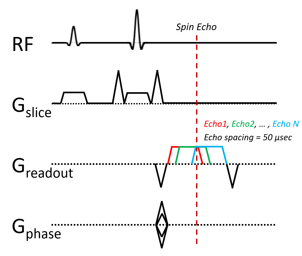
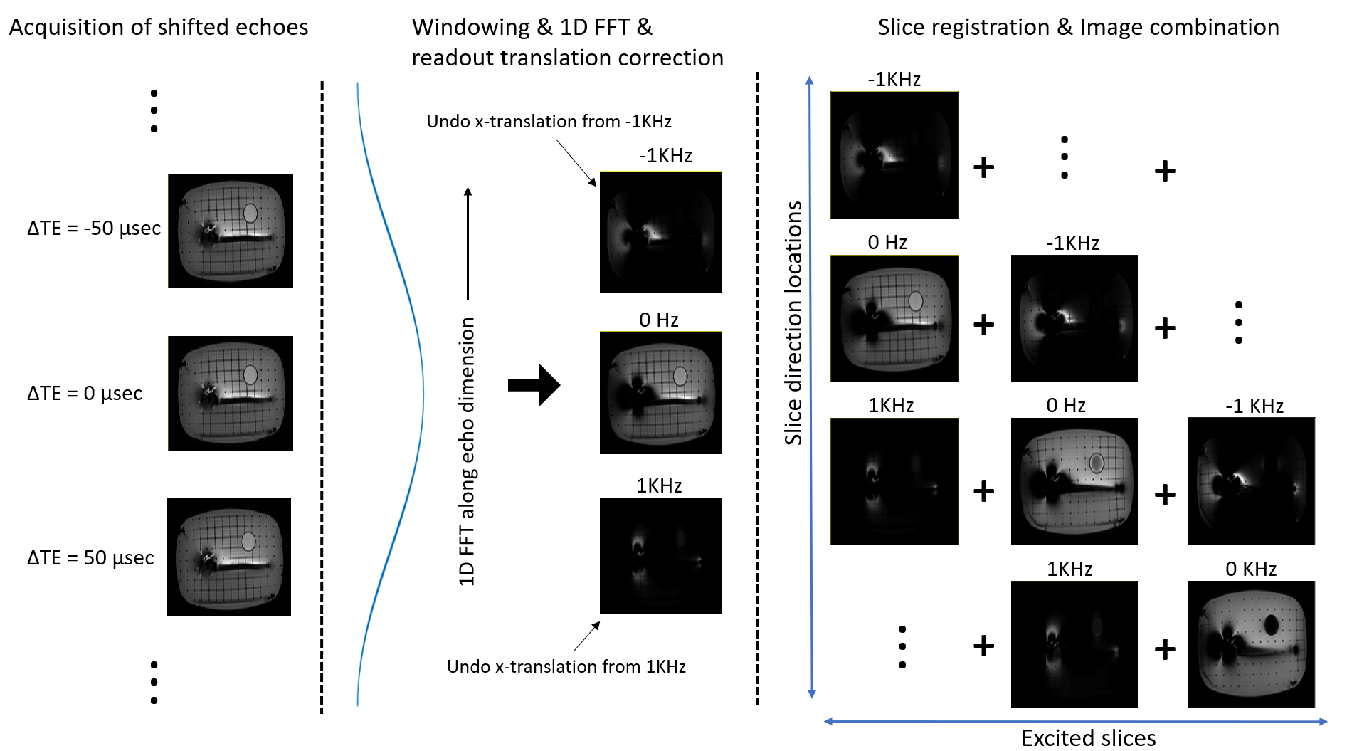
We adopted a spectroscopic 2D multi-slice acquisition as plotted in Figure 1 and the reconstruction process is summarized in Figure 2. Each slice is assumed to have multi-spectral components that correspond to out-of-slice excitation based on off-resonance. We repeat the acquisition of each slice with a range of echo-shifts to measure the spectral distribution by 1D Fourier transform along the echo-time dimension. Knowledge of the frequency enables correction of both the slice-direction and readout-direction displacement.For example, if I(T) denotes a 2D image I with echo shift of T µsec and I’(F) denotes a 2D image with off-resonance frequency of F kHz, then 1D Fourier transform of I(-500), I(-400), I(-300), … , I(200), I(300), I(400) results in I’(-5), I’(-4), …, I’(4). Note that we applied a Hanning window before Fourier transform to suppress Gibbs ringing. The distance in the slice direction between I’(F) and the nominal slice location (I(0)) is estimated to be F/BWRF * (slice thickness) where BWRF is the RF bandwidth. After the slice registration and translation, the spectral images for each slice location were combined with magnitude summation.
We conducted an imaging experiment with a shoulder implant phantom with titanium shaft and cobalt chromium head using a 3T GE Premier scanner and a single channel T/R coil. We compared the images from MAVRIC-SL for the conventional 3D MSI, a 2D spin-echo (SE), and the proposed SEMSI sequences. Imaging parameters for MAVRIC-SL/2D SE/SEMSI are as follows: TR(ms) = 4600/700/700, TE(ms) = 6.2/10.9/10.9, Bandwidth(KHz) = ±125/±125/±125, FOV = 26x18.2 MATRIX = 256/90, ETL = 24/1/1, Slice thickness(mm) = 4/4/4. The RF bandwidth/echo shift spacing/number of echoes were 1kHz/50usec/21 for SEMSI.
Results
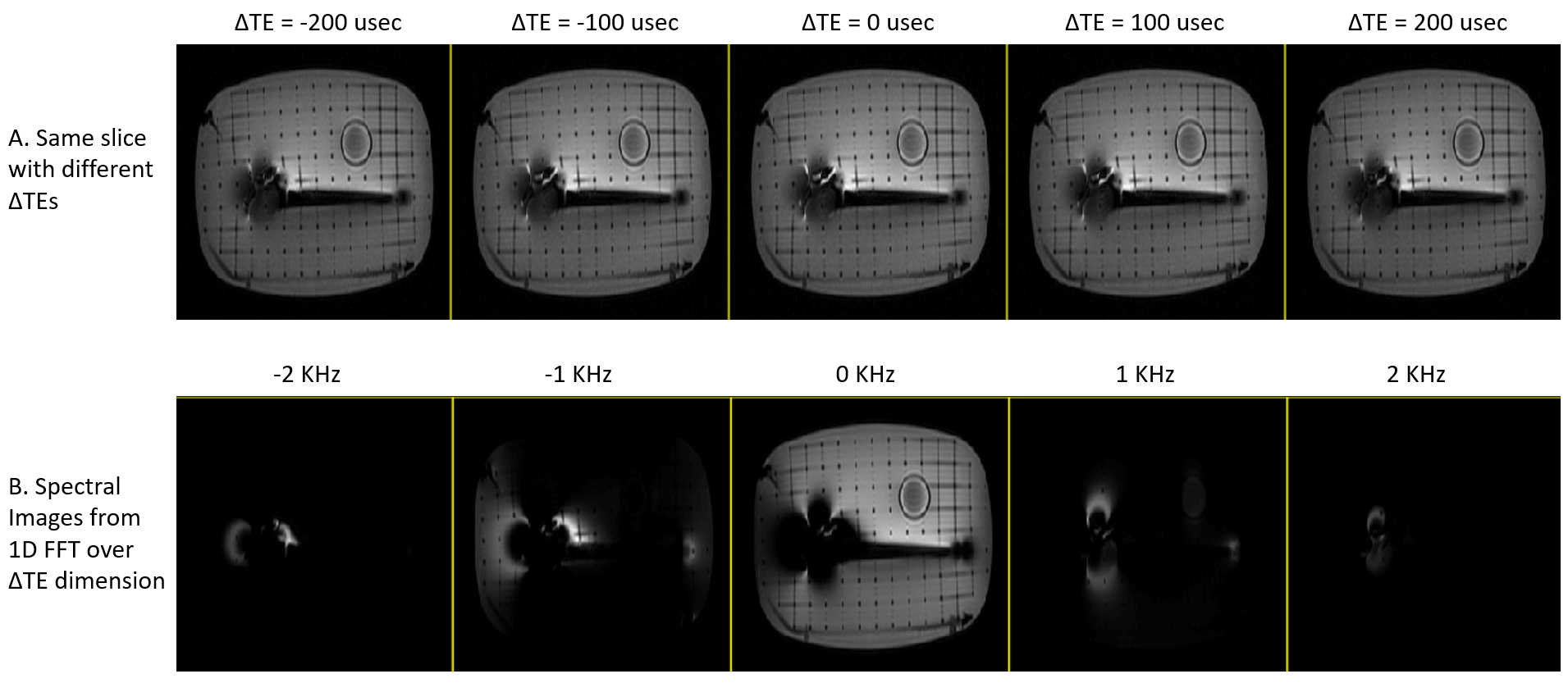
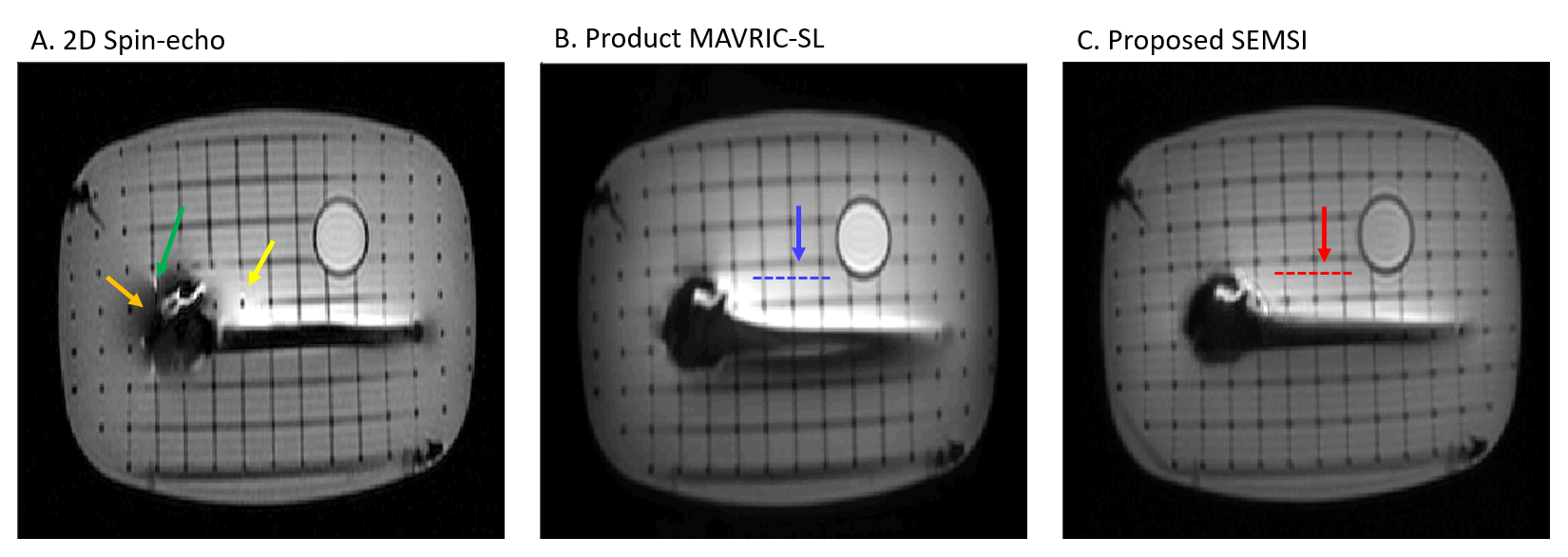
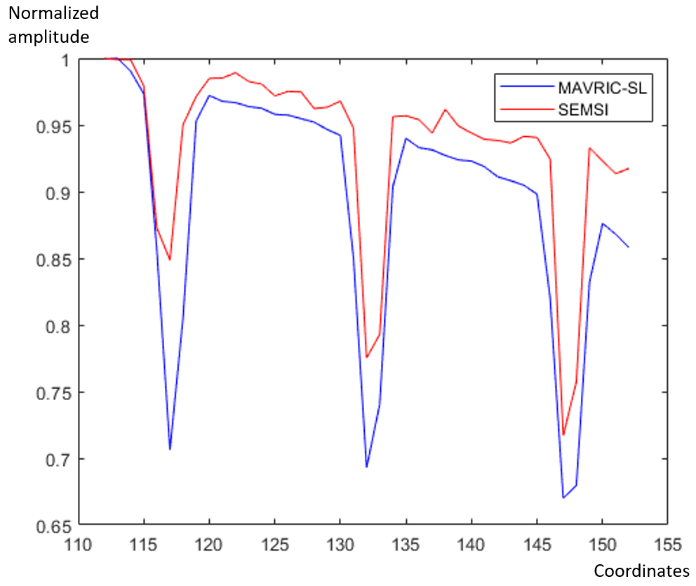
Figure 3 shows the images of different echo shifts and resulting spectral images for a single slice location. The excited signal on the off-resonance spectral images at -2, -1, 1, 2kHz follows the dipole patterns observed in the 3D (z-resolved) images of an excited slice/bin in conventional 3D MSI methods, since slice distortion is proportional to off-resonance. Figure 4 compares final slice images at the same location from 2D SE, MAVRIC-SL, and SEMSI sequences. Even though 2D SE adopted the same high readout bandwidth (±125 KHz) as in MAVRIC-SL and SEMSI, signal from other slices (yellow arrow), signal loss (orange arrow), and pile-up (green arrow) still occur. The proposed SEMSI image shows comparable artifact suppression to the MAVRIC-SL image, while preserving sharper edge information as illustrated in the line profiles (Figure 5). Additionally, shading artifacts both near and away from the metal are reduced in SEMSI, possibly due to flatter excitation profiles.Discussion
We present a novel imaging method that can offer off-resonance correction near metallic implants without global blurring as in the conventional MSI methods with x-y-z spatial encoding and VAT. VAT limits the in-plane artifact, but also creates blurring because it globally forces a frequency spread over the RF pulse bandwidth. VAT-induced blurring is exacerbated if a lower readout bandwidth is used. Instead, spectral encoding adopted in our method (x-y-f encoding) resolves the spectral distribution, where within each excited slice/bin, pile-up and translation artifacts can be easily mitigated or resolved. Our method does not create extra frequency spread in the on-resonance area away from metal, and thus does not incur unnecessary global blurring. The accuracy of slice-registration for spectral images can be further improved by the optimization of the RF bandwidth and profile. The interleaving of multiple echoes and advanced sampling techniques will improve efficiency, and the readout bandwidth can be reduced to improve SNR without inducing additional blurring that would result when using VAT.Conclusion
We introduce a novel acquisition/reconstruction algorithm for off-resonance artifact correction near metallic implants using spectral encoding for grouping signal of narrow spectrum, which can be re-registered to the correct location based on the associated resonance frequency. Phantom experiments show the promise of our method to achieve off-resonance correction without causing global blurring as in conventional methods.Acknowledgements
This work was supported by NIH K08NS094547 and GE Healthcare.References
1. Koch KM, et al. (2011) Imaging near metal with a MAVRIC-SEMAC hybrid. Magn Reson Med 65(1):71-82.
2. Lu W, Pauly KB, Gold GE, Pauly JM, & Hargreaves BA (2009) SEMAC: Slice Encoding for Metal Artifact Correction in MRI. Magn Reson Med 62(1):66-76.
3. Cho ZH, Kim DJ, & Kim YK (1988) Total inhomogeneity correction including chemical shifts and susceptibility by view angle tilting. Med Phys 15(1):7-11.
Figures