0627
System for Validating MRI-based Myocardial Stiffness Estimation Techniques Using 3D-Printed Heart Phantoms1Mechanical Engineering, Stanford University, Stanford, CA, United States, 2Radiology, Veterans Administration Health Care System, Palo Alto, CA, United States, 3Radiology, Stanford University, Stanford, CA, United States, 4Bioengineering, Stanford University, Stanford, CA, United States, 5Computer Science, Technical University of Munich, Garching, Germany
Synopsis
Cardiac MRI and finite element based techniques can be used to obtain subject-specific myocardial material properties. Verifying the accuracy and precision of these techniques requires overcoming the challenge of obtaining ground-truth in vivo myocardial stiffness estimates. This work presents a highly controlled in vitro diastolic filling setup incorporating a 3D-printed heart phantom developed with myocardial tissue-mimicking material of known mechanical and MRI properties. The setup enables acquisition of the data needed to estimate myocardial stiffness in computational models: phantom geometry, loading pressures, boundary conditions, and filling strains. This setup is designed to enable extensive validation of myocardial stiffness estimation frameworks.
Introduction
Ventricular remodeling contributes to both decreased cardiac function and heart failure (HF). Increased myocardial stiffness is a significant consequence of remodeling [1], but currently there exists no accepted clinical method to measure changes in myocardial material properties.Constitutive modeling is one method of obtaining myocardial material properties. Cardiac MRI (CMR) combined with a finite element modeling (FEM) framework has been used to obtain patient-specific ventricular stiffness [2]. However, quantifying the accuracy and precision of these CMR and FEM-based stiffness estimation techniques is relatively understudied due to the challenge of obtaining ground-truth measures of in vivo myocardial tissue properties. Validation of these methods necessitates the development of a highly controlled in vitro stiffness estimation framework that incorporates a phantom of known stiffness properties.
The aims of this study were to: (1) develop heart phantoms using myocardium-mimicking materials of known mechanical and MRI properties; and (2) demonstrate the feasibility of an MRI compatible in vitro diastolic filling setup for estimating phantom ventricular mechanics and stiffness.
Methods
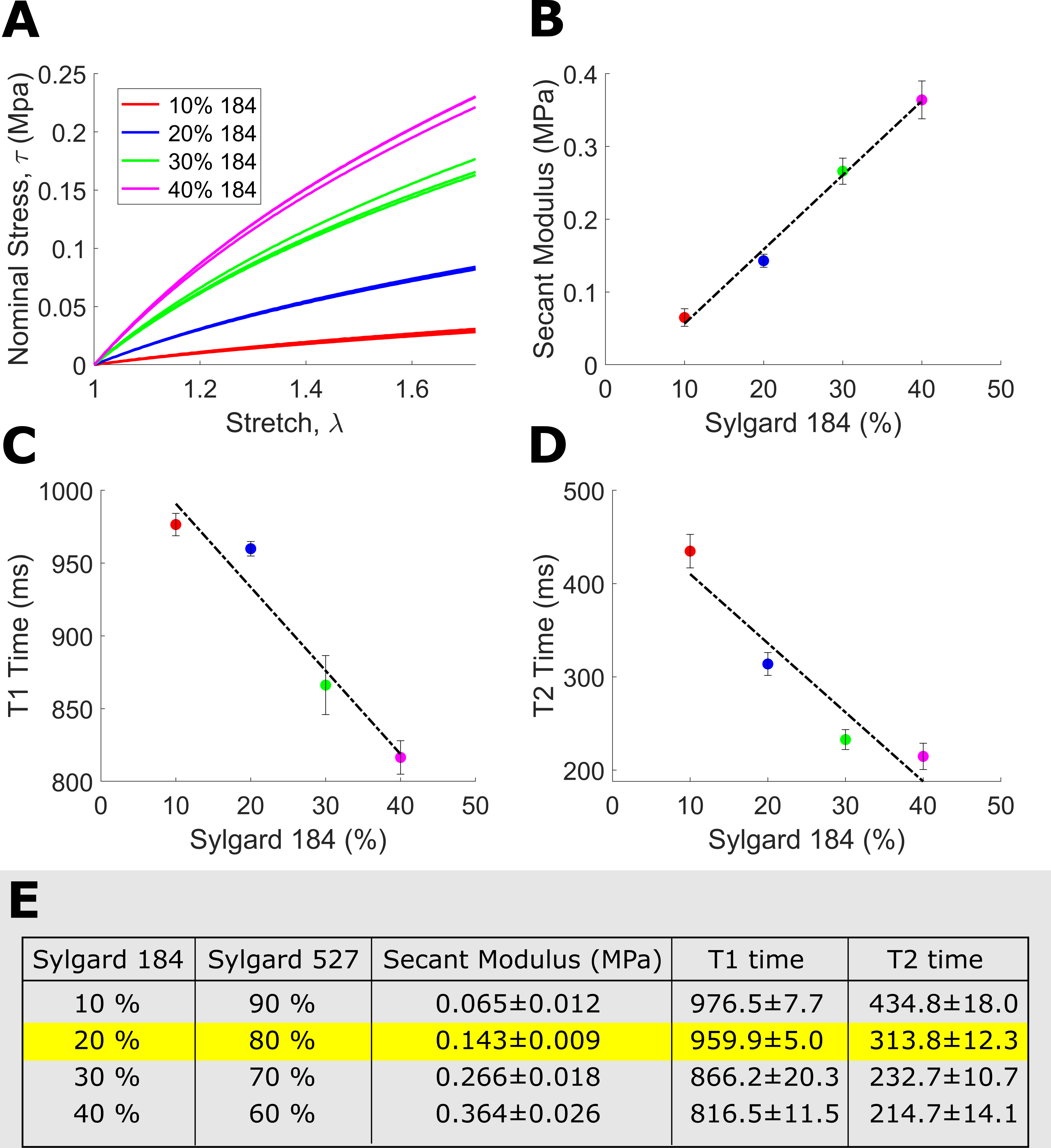
Tissue-Mimicking Material Selection: Sylgard blends (fig.1) were mechanically characterized according to the ASTM D412 standard [3] using an Instron 5848 Microtester (100N load cell). MRI relaxation properties were measured through T1-mapping (MOLLI 5-3-3, spatial resolution 1.00×1.00×5.0mm3) and T2-mapping (T2-prep FLASH; flip angle 12º; spatial resolution, 1.00×1.00×5.0mm3).Phantom Development: High-resolution T1-weighted images (fig.2) from a healthy ex vivo porcine heart (geometrically restored to its in vivo mid-diastasis geometry) [4] was used to generate a mesh model of the heart walls. The geometric model was modified (Fusion 360, Autodesk) to incorporate ventricular ports. The left ventricular (LV) and right ventricular (RV) blood pool were segmented and converted into sterolithography (STL) files, then 3D printed (Ultimaker 3Ext) with water-soluble polyvinyl acid (PVA). An STL negative for casting was created from the whole heart segmentation, then 3D printed using polylactic acid (PLA). A heart phantom was then cast using a blend of 20% Sylgard184 and 80% Sylgard527.
Inflation Flow Loop: The final model was embedded within a flow loop (fig.3) controlled by a programmable MR-compatible linear motion stage (MR-1A-XRV2, Vital Biomedical Technologies). The loop was designed to reproduce in vivo diastolic LV filling. MR-compatible pressure transducers (Micro-Tip SPR 350S, Millar) in the ventricular cavities enable acquisition of filling pressures.
Imaging Methods: All in vitro images were collected on a 3T (Skyra, Siemens). First, a static reference imaging volume spanning the entire phantom was acquired (3D SPGR; TE/TR, 2.17/5.5ms; flip angle, 20º; isotropic 1.00mm3), then a cardiac-like late-diastolic filling cycle (sinusoidal flow: 13 mL/cycle mean, 1s period) was induced. The phantom motion was imaged with an externally triggered cardiac tagging sequence (SPAMM; TE/TR, 3.08/53.04ms; flip angle, 10º; spatial resolution, 1.00×1.00×8.0mm3; 17 phases per cardiac cycle, 5mm grid tags) with slices spanning the whole phantom.
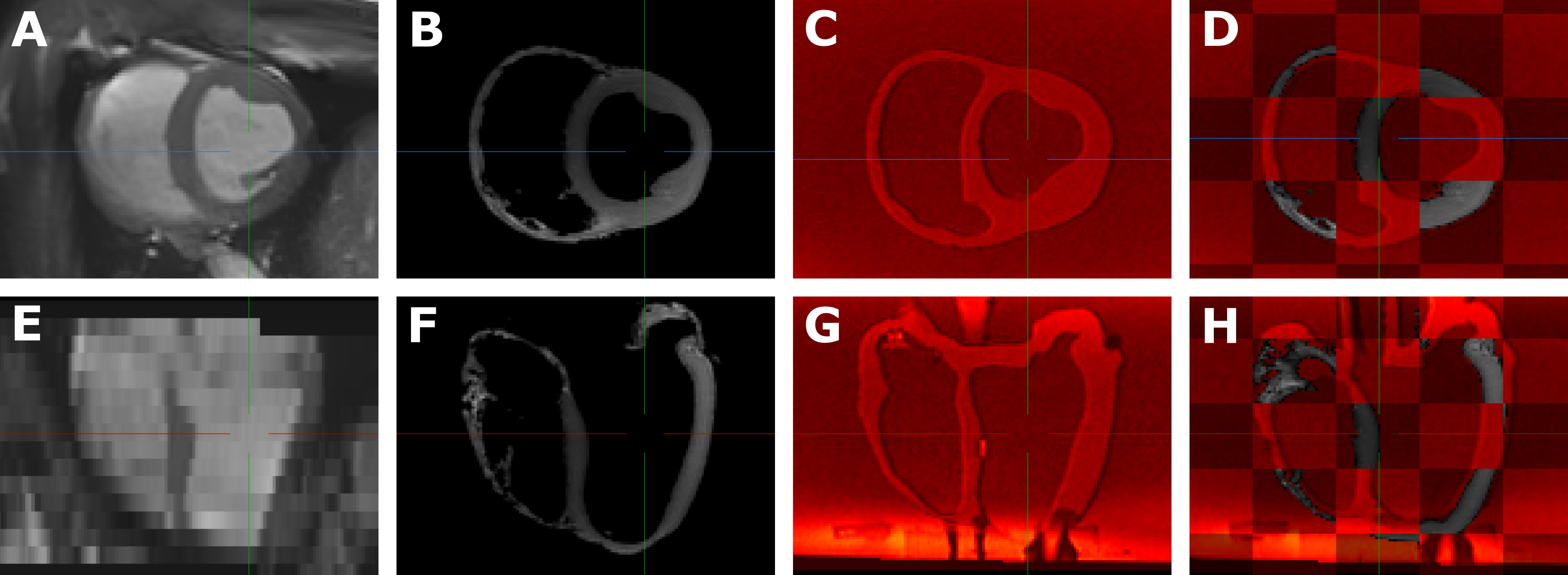
Geometric Accuracy: Phantom geometric accuracy was assessed qualitatively using landmark-based rigid registration of in vivo balanced Steady State Free Precession images (bSSFP; TE/TRes, 1.58/17.9ms; flip angle, 38º; spatial resolution, 1.18×1.18×8.0mm3; mid-diastasis cardiac phase) to in vitro 3D SPGR images at their native voxel resolution using MITK Workbench. Landmarks consisted of four points in the most basal slice (septal wall center, anterior papillary muscle, free wall center, posterior papillary muscle) and four similar points at a slice near the apex.
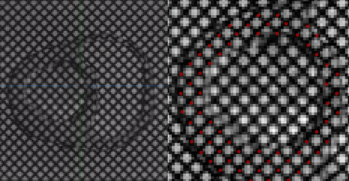
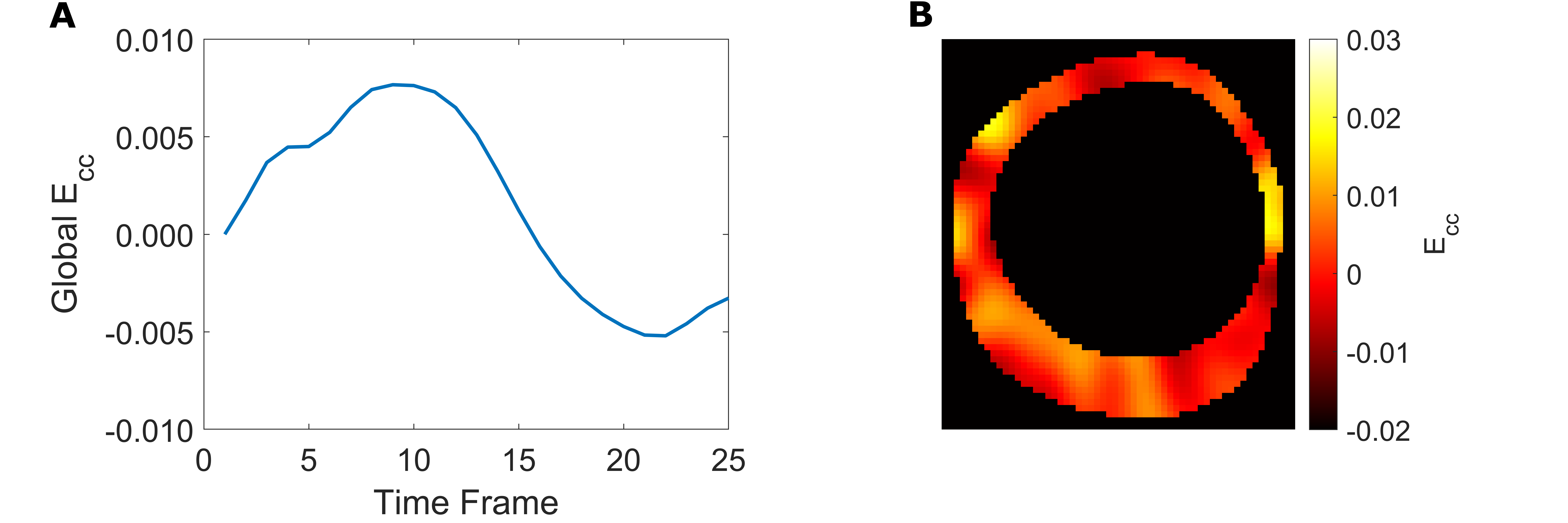
Quantitative Strain Analysis: Tag lines were tracked with a neural-net based algorithm, which produced displacement curves for tag line intersections [5]. Circumferential strain (Ecc) was calculated from displacements with a radial basis function interpolant [6].
Results
Mechanical and MRI properties of Sylgard blends are reported in figure 1 (fig.1E table). Though the blend containing 10% Sylgard184 exhibits the most comparable mechanical and MR properties to myocardium [7,8] (fig.1E table), the blend containing 20% Sylgard184 was the more feasible phantom material choice due to easier workability.Image overlays between registered in vitro, in vivo and ex vivo images demonstrate that the phantom development procedure adequately reproduces the in vivo and ex vivo geometry (fig.2). Tagged image acquisition and analysis demonstrate the feasibility of obtaining quantitative strain measures during diastolic inflation. Strain followed a sinusoidal pattern (like the filling flow pattern) with peak global LV Ecc of 0.0076 (fig.5A) and peak displacement of 1.05mm.
Discussion
Tensile testing of samples allowed for ground-truth phantom material stiffness estimates. Future work will use this system to estimate the phantom’s material stiffness as proof-of-principle that material stiffness estimation is feasible in vivo. Different subject-specific heart phantoms based on in vivo images can be manufactured, with phantom stiffness tuned to a known value. This enables the characterizing of the accuracy and precision of the stiffness estimation framework.Although the phantom material properties are comparable to myocardium, in vivo heart anisotropy was not replicated. Moreover, sylgard is insensitive to diffusion imaging. The ability to directly 3D-print soft, MRI visible materials would speed up the experimental system development, eliminating the need to cast the heart phantoms.
Conclusion
This work demonstrates that subject-specific heart phantoms with diastolic myocardium-mimicking properties can be developed and incorporated within an MRI-compatible diastolic filling setup for estimating phantom material stiffness.Acknowledgements
This project was supported by NIH R01 HL131823 to DBEReferences
1. Azevedo, Paula S., Bertha F. Polegato, Marcos F. Minicucci, Sergio A. R. Paiva, Leonardo A. M. Zornoff, Paula S. Azevedo, Bertha F. Polegato, Marcos F. Minicucci, Sergio A. R. Paiva, and Leonardo A. M. Zornoff. “Cardiac Remodeling: Concepts, Clinical Impact, Pathophysiological Mechanisms and Pharmacologic Treatment.” Arquivos Brasileiros de Cardiologia 106, no. 1 (January 2016): 62–69.
2. Wang, V.Y., P.M.F. Nielsen, and M.P. Nash. “Image-Based Predictive Modeling of Heart Mechanics.” Annual Review of Biomedical Engineering 17, no. 1 (2015): 351–83. https://doi.org/10.1146/annurev-bioeng-071114-040609.
3. ASTM Standard C33, 2003, "Specification for Concrete Aggregates," ASTM International, West Conshohocken, PA, 2003, DOI: 10.1520/C0033-03, www.astm.org.
4. Cork, Tyler E., Luigi E. Perotti, Ilya A. Verzhbinsky, Michael Loecher, and Daniel B. Ennis. “High-Resolution Ex Vivo Microstructural MRI After Restoring Ventricular Geometry via 3D Printing.” In Functional Imaging and Modeling of the Heart, edited by Yves Coudière, Valéry Ozenne, Edward Vigmond, and Nejib Zemzemi, 177–86. Lecture Notes in Computer Science. Cham: Springer International Publishing, 2019. https://doi.org/10.1007/978-3-030-21949-9_20.
5. Loecher M, Perotti LE , Ennis DB. Cardiac Tag Tracking with Deep Learning Trained with Comprehensive Synthetic Data Generation. ISMRM 28th Annual Meeting, Paris, France (Virtual Conference), 2020
6. Bistoquet, Arnaud, John Oshinski, and Oskar Škrinjar. "Myocardial deformation recovery from cine MRI using a nearly incompressible biventricular model." Medical image analysis 12.1 (2008): 69-85
7. Demer, L. L., and F. C. Yin. “Passive Biaxial Mechanical Properties of Isolated Canine Myocardium.” The Journal of Physiology 339, no. 1 (1983): 615–30. https://doi.org/10.1113/jphysiol.1983.sp014738.
8. Kim, Pan Ki, Yoo Jin Hong, Dong Jin Im, Young Joo Suh, Chul Hwan Park, Jin Young Kim, Suyon Chang, et al. “Myocardial T1 and T2 Mapping: Techniques and Clinical Applications.” Korean Journal of Radiology 18, no. 1 (2017): 113–31. https://doi.org/10.3348/kjr.2017.18.1.113.
Figures
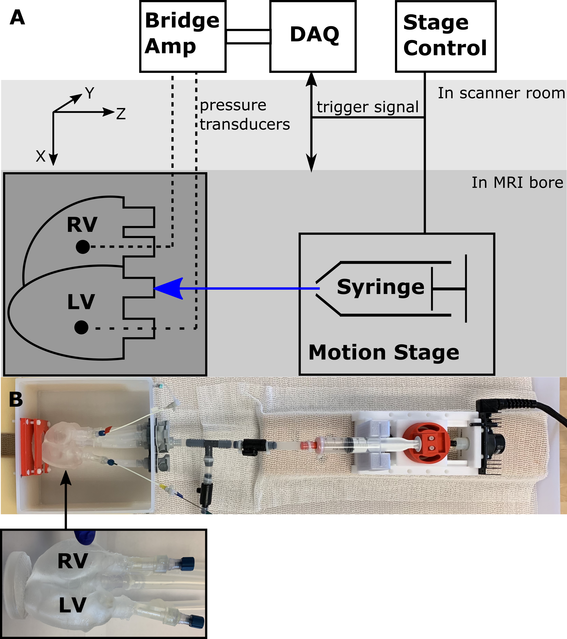
(A) Schematic of experimental setup (B) Picture of experimental setup with heart phantom highlighted.
The RV is kept at a constant volume with reference pressure set to mimic the relatively smaller pressures and pressure variations in the RV, compared to the LV seen in vivo. Each ventricle is connected in a closed loop. The LV is connected in a closed loop with an inflation system. The fluid volume in each loop is fixed and the MR compatible motion stage is used to actuate a fluid filled syringe within the LV loop, modulating LV pressures and volumes. The phantom is fixed at the apex