0565
PNS optimization of a high-performance asymmetric gradient coil for head imaging1Martinos Center for Biomedical Imaging, Boston, MA, United States, 2Harvard Medical School, Boston, MA, United States, 3Computer Assisted Clinical Medicine, Medical Faculty Mannheim, Heidelberg University, Mannheim, Germany, 4Siemens Healthineers, Erlangen, Germany, 5Advanced MRI Technologies, Sebastopol, CA, United States, 6Brain Imaging Center and Helen Wills Neuroscience Institute, University of California, Berkeley, CA, United States, 7Harvard-MIT, Division of Health Sciences and Technology, Cambridge, MA, United States
Synopsis
PNS modeling was utilized during the design stage of a high-strength (Gmax = 200mT/m, Smax = 900 T/m/s) head gradient for 7T fMRI research. The design-stage preview of PNS thresholds and locations allowed alteration of the winding pattern to balance head and body stimulation. This process yielded significantly improved PNS thresholds and increased usability of the coil performance space. The results were validated using PNS experiments in a constructed coil.
Target audience
MRI gradient designers, safety researchers and imaging neuroscientistsPurpose
PNS can significantly limit the usable performance of MRI gradient coils [1-3]. While whole-body gradients are traditionally considered the most prone to PNS (due to the large body area exposed), the latest generation of asymmetric head-only gradients is also restricted by PNS [4]. Here we describe the design strategy and PNS performance optimization of a high-linearity asymmetric head-only gradient coil developed for high resolution EPI based fMRI and brain research for NIH BRAIN project (U01EB025162). PNS calculations during the design stage allowed winding optimization to balance PNS between the head and body, yielding significantly improved PNS thresholds to increase the coil’s usable performance.Methods
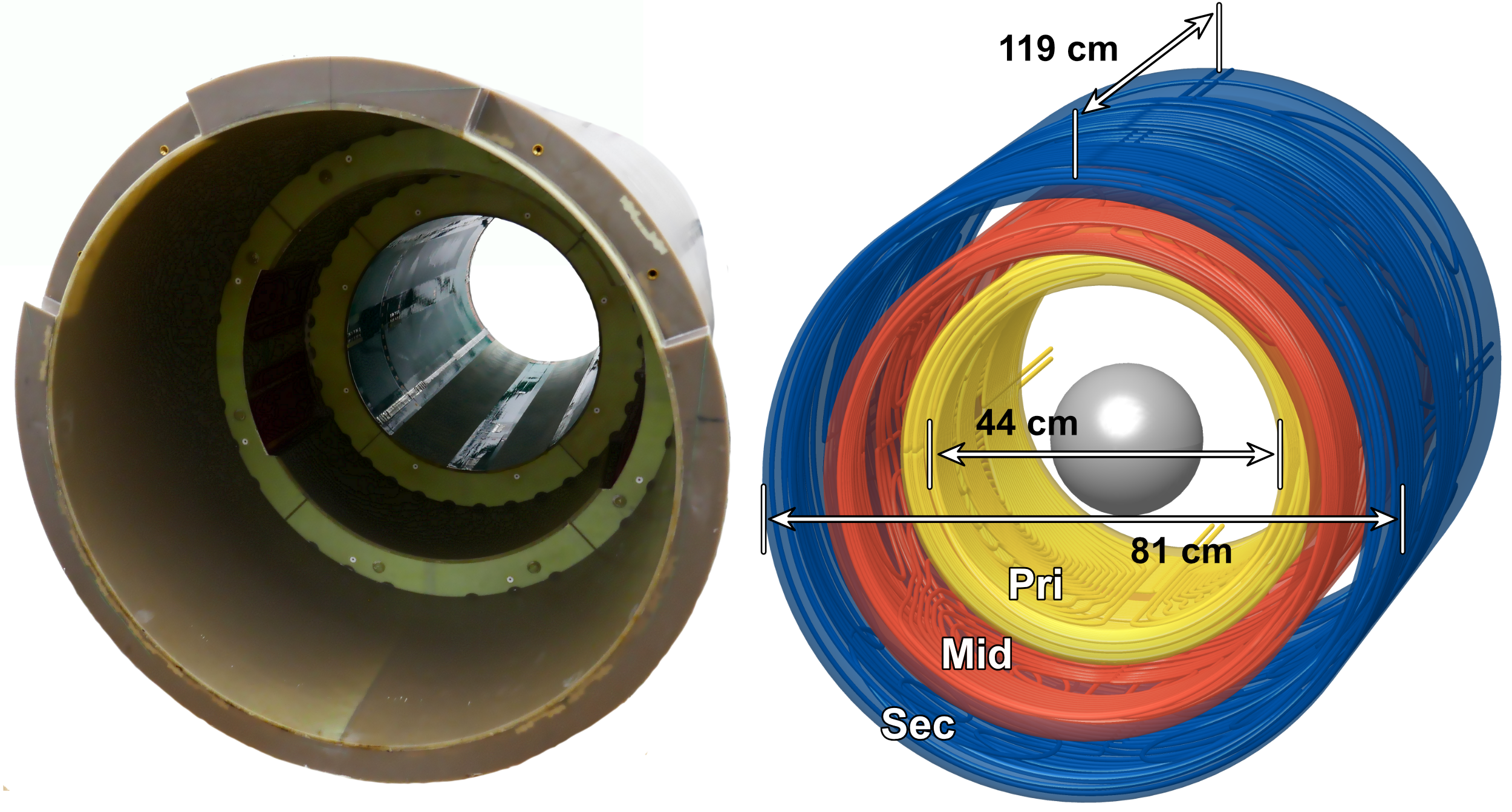
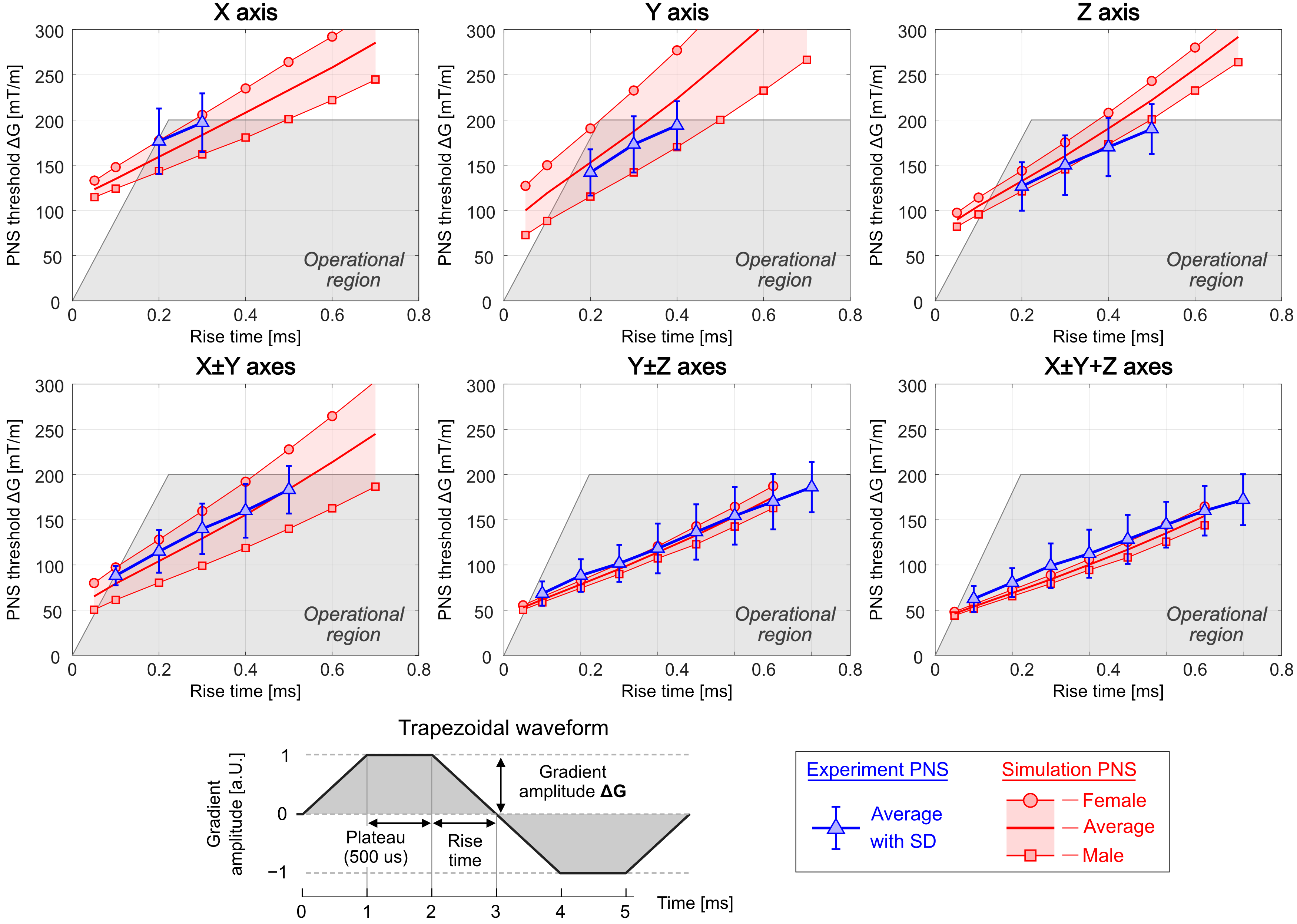
Design goal, PNS modeling and optimization: The design targets for the “Impulse” 7T head gradient (Siemens Healthcare, Erlangen, Germany) sought high gradient linearity (<10% on a 20 cm DSV), a relatively large inner diameter (44 cm) and high strength and slew rate (200 mT/m and up to 900 T/m/s per axis); all parameters known to exacerbate PNS effects, potentially limiting the usable performance. We applied our PNS modeling methods [5-8] in the design phase to analyze different candidate coils and identify design aspects with beneficial impact on PNS (higher thresholds) while observing the many other engineering goals. We examined variations in coil dimensions, number of winding layers, size and linearity of the FOV, as well as the coil’s asymmetry. Adjusting the latter provided a way to balance expected PNS in the head and body and maximize thresholds of the worst-case PNS.PNS experiments: After coil construction, a detailed experimental PNS study was performed at Siemens Healthcare under ethics approval and with written informed consent using 33 volunteers (16 males, 17 females), average age of 58.4 ± 13.1 years (min. 21, max. 74), weight 77.6 ± 13.5 kg (min. 52, max. 110), and height 173.5 ± 9.4 cm (min. 154, max. 191). The stimulation study utilized a 128 trapezoidal pulse prototype sequence with varying rise times (10−10,000 us) and constant 500 us flattop. This waveform was applied to X, Y and Z as well as multiple axes simultaneously with varying polarity combinations (X±Y, Y±Z, X±Y+Z). For each subject, both combination polarities (i.e., X+Y and X−Y) were assessed for a single rise time. The full measurement series of rise-times was performed for both the single axis cases and for the combination polarity yielding the lowest thresholds. The PNS perception threshold amplitude and perceived locations were recorded. Although a pre-PNS-optimized coil was not constructed for in-vivo comparisons, we attempt to assess the optimization by comparing to reported thresholds in other head gradients.
Results
Figure 1 shows a photograph and rendering of the 3-layer winding pattern of the final Impulse gradient. The additional degrees-of-freedom from the intermediate layer were helpful for balancing head and body PNS without significant sacrifices in other constraints. Additional coil characteristics are summarized in Fig. 3.Figure 2 shows average and SD experimental PNS and simulated PNS thresholds for all single axis and multi-axes cases. Comparing experimental and simulated average PNS thresholds showed average differences between 5.3% (Y±Z axes) and 11.7% (X axis).
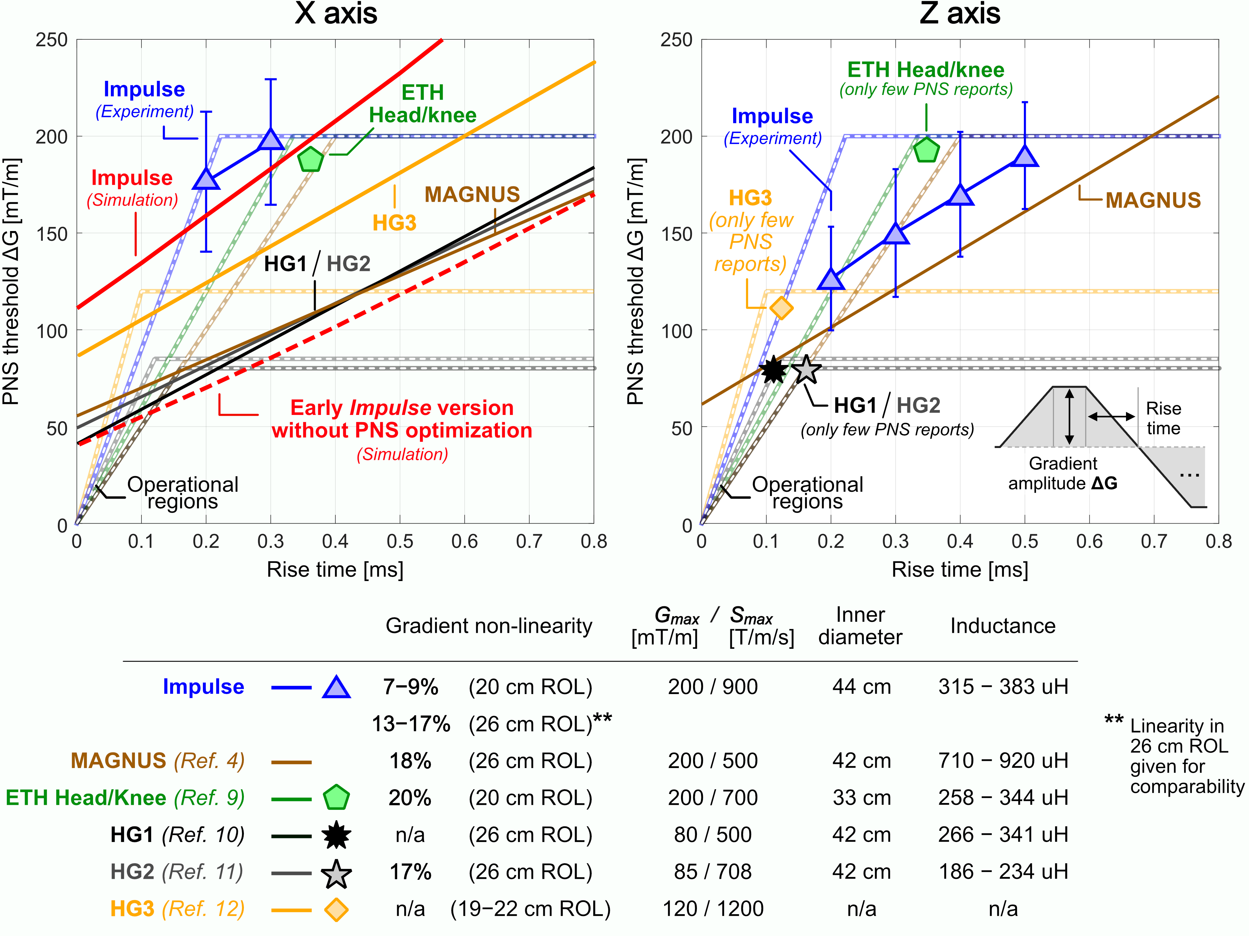
Figure 3 shows experimental PNS characteristics and coil properties of the Impulse coil and five previously published head gradients: the “ETH Head/knee” coil [9], the “MAGNUS” coil [4] and “HG1”, ”HG2”, and ”HG3” coils [10,11,12]. We additionally show the simulated PNS thresholds for the final Impulse coil and an earlier version without PNS optimization. Optimization provided an approx. 2X PNS improvement. Although the previously published coils likely have differing design goals, the Impulse coil’s PNS optimized design showed higher thresholds compared to these designs.
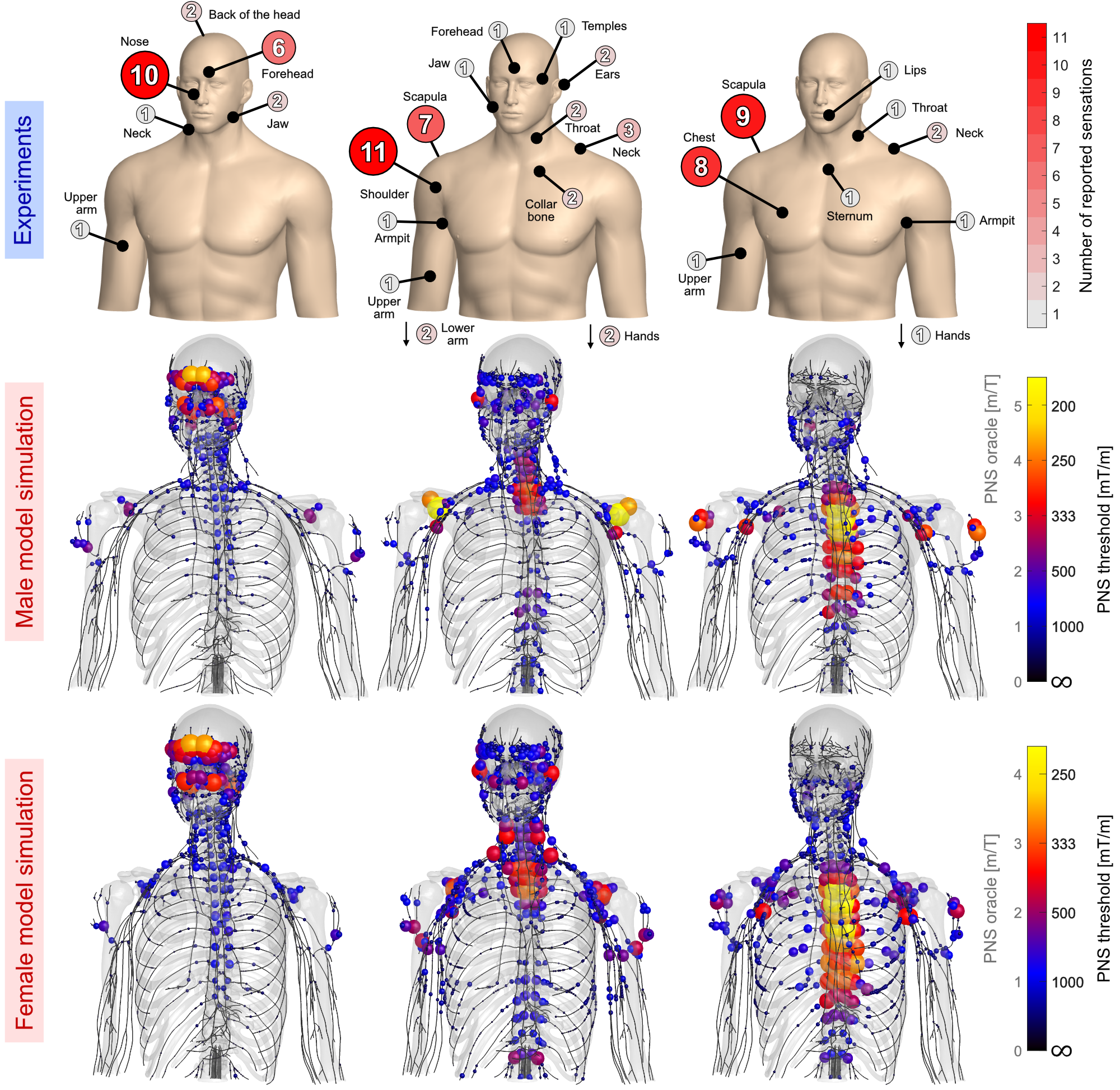
Figure 4 (top) summarizes reported sites of perceived stimulation for the three Impulse axes and simulated PNS hot-spot maps in terms of PNS oracle (reciprocal PNS threshold) showing relatively good agreement between experimentally reported and simulated sites. The X-axis mostly stimulated nerves in the forehead and the nose in both experiments and simulations. The Y-axis stimulation sites were located in the shoulder and scapula (as predicted by the PNS model). The model also predicted activation of the upper intercostal nerves, likely responsible for reported perceptions in the neck, throat and collarbone. For the Z-axis, modeling predicted activation in the upper intercostal nerves, predominantly the cervical plexus (innervating the scapula) and the thoracic intercostal nerves (innervating the chest muscle and neck).
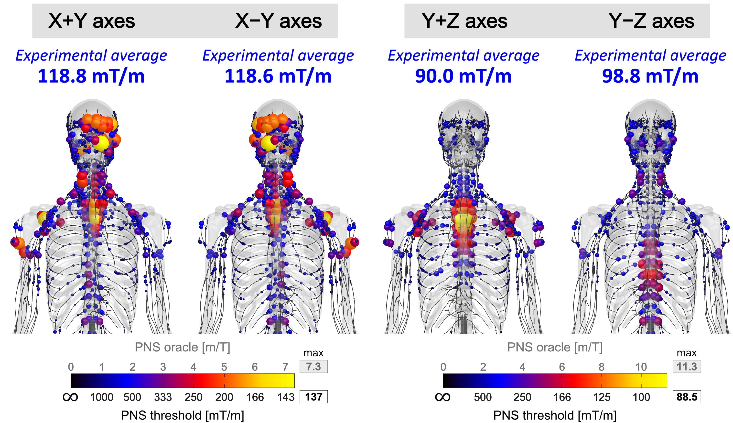
Figure 5 shows predicted PNS hot-spots for axes combinations X±Y and Y±Z. Flipping the polarity for the X±Y superposition led to similar but mirrored activation maps. This was in agreement with experiments that showed similar thresholds for X+Y (118.8 ± 26.6 mT/m) and X-Y (118.6 ± 24.8 mT/m). Flipping the polarity for Y±Z improved PNS in both simulation and experiments (90.0±18.0 mT/m to 98.8±20.4 mT/m) although the difference was less pronounced in the experiments than simulations.
Conclusion
We utilized PNS modeling during the design phase of a high-strength head gradient for 7T human neuroimaging research. Simulating PNS thresholds and locations of intermediate winding layouts allowed alteration of the winding pattern to balance head and body stimulation, yielding substantially improved PNS thresholds and thus increased usable coil performance space.Acknowledgements
Research reported in this publication was supported by the National Institute of Biomedical Imaging and Bioengineering, and the National Institute for Mental Health of the National Institutes of Health under award numbers R24MH106053, U01EB026996, U01EB025162, U01EB025121, R01EB028250. The content is solely the responsibility of the authors and does not necessarily represent the official views of the National Institutes of Health.References
[1] Feinberg et al., “Pushing the limits of ultra-high resolution human brain imaging with SMS-EPI demonstrated for columnar level fMRI“, NeuroImage. vol. 164, pp155-163, 2018
[2] Setsompop et al., “Pushing the limits of in vivo diffusion MRI for the human connectome project”, NeuroImage, vol. 80, pp. 220 – 233, 2013
[3] McNab et al., “The human connectome project and beyond: Initial applications of 300 mT/m gradients” NeuroImage, vol. 80, pp. 234 – 245, 2013
[4] Tan et al., “Peripheral nerve stimulation limits of a high amplitude and slew rate magnetic field gradient coil for neuroimaging”, Magnetic resonance in medicine, vol. 83, no. 1, pp. 352–366, 2020.
[5] Davids et al., “Predicting magnetostimulation thresholds in the peripheral nervous system using realistic body models”, Sci Rep, vol. 7, no. 1, p. 5316, 2017.
[6] Davids et al., "Prediction of peripheral nerve stimulation thresholds of MRI gradient coils using coupled electromagnetic and neurodynamic simulations", Magnetic resonance in medicine 81.1 (2019): 686-701.
[7] Davids et al. “Optimizing selective stimulation of peripheral nerves with arrays of coils or surface electrodes using a linear peripheral nerve stimulation metric”, J Neural Eng, vol. 17, no. 1, p. 016029, 2020.
[8] Davids et al., "Optimization of MRI Gradient Coils with Explicit Peripheral Nerve Stimulation Constraints", IEEE Transactions on Medical Imaging (in print), 2020.
[9] Weiger et al., “A high-performance gradient insert for rapid and short-T2 imaging at full duty cycle”, Magnetic resonance in medicine, vol. 79, no. 6, pp. 3256–3266, 2018.
[10] Mathieu et al., "Preliminary evaluation of a high performance gradient coil for 3T head specialty scanner", Proceedings of the 21st Annual Meeting of the International Society of Magnetic Resonance in Medicine. 2013.
[11] Lee et al. "Peripheral nerve stimulation characteristics of an asymmetric head‐only gradient coil compatible with a high‐channel‐count receiver array", Magnetic resonance in medicine 76.6 (2016): 1939-1950.
[12] Wade et al., "Peripheral nerve stimulation thresholds of a high performance insertable head gradient coil", Proceedings of the 24th Annual Meeting of ISMRM, Singapore. 2016.
Figures