0563
Towards 8ch multi transmit with high power ultrasonic spirals and 72ch receive setup for ultimate spatial encoding at 7T
Dimitri Welting1, Edwin Versteeg1, Ingmar Voogt2, Joost van Straalen3, Martijn Heintges3, Marco Rietveld3, Jeroen C.W. Siero1,4, and Dennis W.J. Klomp1
1Radiology, University Medical Center Utrecht, Utrecht, Netherlands, 2Wavetronica, Utrecht, Netherlands, 3Prodive Technologies, Son, Netherlands, 4Spinoza Centre for Neuroimaging Amsterdam, Amsterdam, Netherlands
1Radiology, University Medical Center Utrecht, Utrecht, Netherlands, 2Wavetronica, Utrecht, Netherlands, 3Prodive Technologies, Son, Netherlands, 4Spinoza Centre for Neuroimaging Amsterdam, Amsterdam, Netherlands
Synopsis
Here we propose a setup to boost spatiotemporal encoding for fMRI in the human brain using high dense receiver arrays (72ch) and fast gradients (6000T/m/s). Moreover, we demonstrate that the operation frequency of a high-end gradient amplifier can be increased to ultrasonic frequencies so to avoid unpleasant acoustic noise. By using this amplifier with 8 transceivers, 64 receivers and a 2-axis cooled gradient coil, a light weight setup is constructed for operation in a 7 Tesla MRI system for fMRI experiments in the human brain.
Introduction
Layer and columnar fMRI is within reach at ultra-high fields and can be used to record brain function at the mesoscopic (<1mm) spatial scale1,2. Such high-resolution requires substantial spatial encoding power (<0.5mm isotropic) at subsecond sampling times while maximizing (temporal) SNR. Here we propose a new hardware setup for 7T that maximizes both RF encoding (72 channels) as well as gradient encoding (next to the X,Y,Z body gradients, 2 extra gradient axis to drive at 5000T/m/s as spirals without causing PNS) to boost spatiotemporal encoding. Moreover, the setup is equipped with an 8 channel dipole transmit coil to mitigate flip angle non-uniformities. To facilitate the high-power gradient drive, we adapted the firmware and end-filter of a high power gradient amplifier to drive the gradients at 21kHz and avoid unpleasant sound perception that generally coincides with increased gradient encoding. Pending IRB approval and reconstruction framework, we show raw MRI data obtained from a phantom at 7T using the entire hardware setup.Methods
The gradient amplifier used is an NG500 1.1 (Prodrive Technologies, Son, Netherlands) as shown in Figure 1a. The FPGA firmware of the gradient amplifier has been modified to allow for a higher frequency range (bandwidth) output. The new firmware modifies the output driver to allow the output current to be a harmonic of the base frequency, increasing the frequency of the gradient amplifier output current up to 32 kHz. This enables the output to be in a forward drive mode, i.e. without any feedback loop. The duty cycle of the pulse-width modulation is controlled by the voltage level at an analog auxiliary input. The internal end-stage filter was removed and brought to the gradient coil as a resonant circuit. The high power gradient waveform is compared to an 18kW audio amplifier we reported on previously3 (Powersoft k20, Italy).The homemade insert gradient has been made with hollow copper windings for a Y- (or X) and a Z-direction magnetic gradient field, creating a 2-axis gradient setup (Fig 2b). Minimal use of epoxy for mechanical support was needed due to the high driving frequency of the insert at 21kHz in combination with the relatively high inertia of the coil. Therefore, the entire setup weighs less than 10kg. Capacitors have been added to the windings to filter unwanted amplifier current noise while enhancing gradient field efficiency by enabling a resonant mode at 21kHz. To allow for high duty cycles and long scan sessions, cooling has been included. A water solution can be pumped through the windings to allow for effective heat dissipation.
To minimize eddy currents, no RF shield was used between the insert gradient and the RF coils. Eight 7T 1H dipoles transceivers, matched to 50 ohm at 298MHz, are integrated into the design and tuned in the presence of the gradient (Fig 1c). Furthermore, a close-fitting 64 channel 7T 1H head coil array (Wavetronica, the Netherlands) was used as a local receive array (Fig 1d).
To measure the performance of the ultrasonic gradient setup, a field camera (Skope, Swiss) has been placed inside the insert gradient.
Results
The output voltage and current as monitored inside the gradient amplifier is shown in Figure 2. At the start and end of the gradient pulse, the dampening effect of the resonant insert gradient is visible. While the gradient amplifier can provide more power to the coil than the previously used audio amplifier, the field cameras show similar temporal behavior and quality when driven with either setup (Figure 3).With the gradient amplifier driven at less than 30% of its maximum, it already provides a 6000T/m/s slew rate at 50mT/m gradient strength (21kHz, Fig 3). With a phantom inside and using the 8 channel transmit coil for spin excitation, signals from the 72 receive channels were recorded by the MRI system during the 21kHz readout, while using the remaining three whole-body gradients to control the gradients for additional spatial encoding. Figure 4 shows a clear 21kHz modulation on top of the echo in k-space.
Discussion
While a fixed resonance at 21kHz is pleasant for sound perception and simplifies cable management, it coincides with limitations in flexibility to setup the MRI experiment due to the fixed encoding speed. Furthermore, no standard MR-sequences exist for 5 gradient axis. The 72 simultaneous channels and high sampling rate needed to capture the 21kHz spirals lead to a relatively high data rate that can complicate standard MRI data pipelines. Setting up the reconstruction line, converging the setup in a more user-friendly appearance and performing safety tests is currently in progress.Conclusion
We successfully increased the operation frequency of a high-end gradient amplifier by altering the firmware and changing the gradient amplifier output filter to a resonant circuit. Moreover, a low-weight setup was constructed that houses 8 transceivers, 64 receivers, 2-axis cooled gradient coil for operation in a 7T MRI system for high-resolution fMRI experiments in the human brain, even providing access for visual stimulation. The operation of the setup was confirmed using field cameras and MR signal detections from 72 receive channels that allow future phantom and safety studies to explore the potential of the setup in maximizing spatiotemporal resolution.Acknowledgements
No acknowledgement found.References
1. Dumoulin, S. O. et al. Neuroimage 168, 345–357 (2018)
2. Huber, L. et al. Neuron 96, 1253-1263.e7 (2017)
3. Versteeg, E. et al. in Proceedings of the 27th Annual Meeting of ISMRM #4586 (2019)
Figures
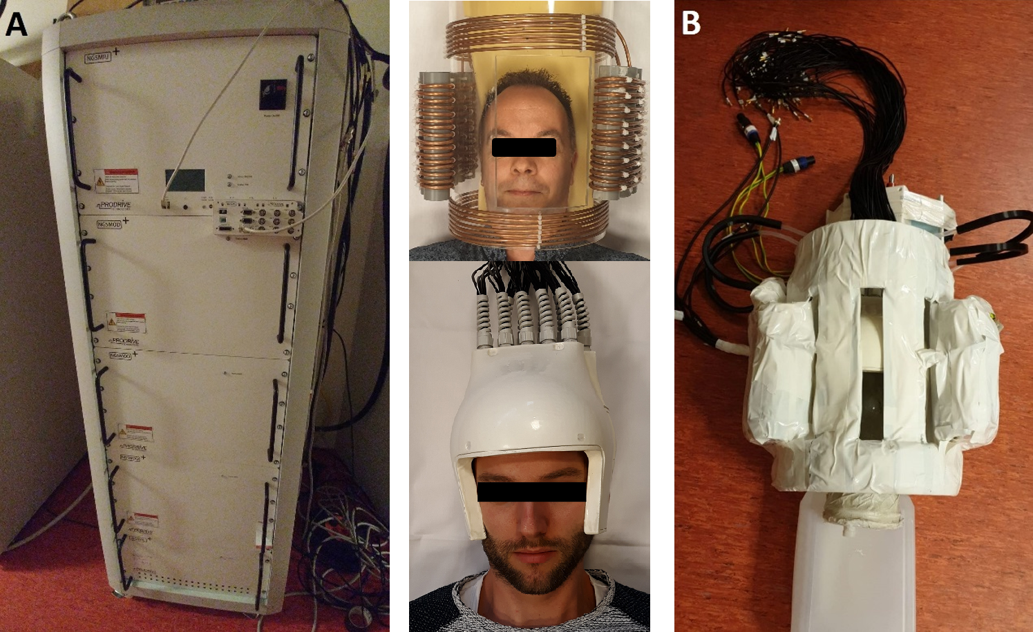
Figure 1: The components of the setup used. The NG500 1.1
gradient amplifier (A). (B) consists of the 2-axis insert gradient, an 8
channel transceive dipole array, a 64 channel receive array and an agar-based head
phantom. The middle images show a more detailed view without insulation tape of
the used insert gradient and receiver coils.
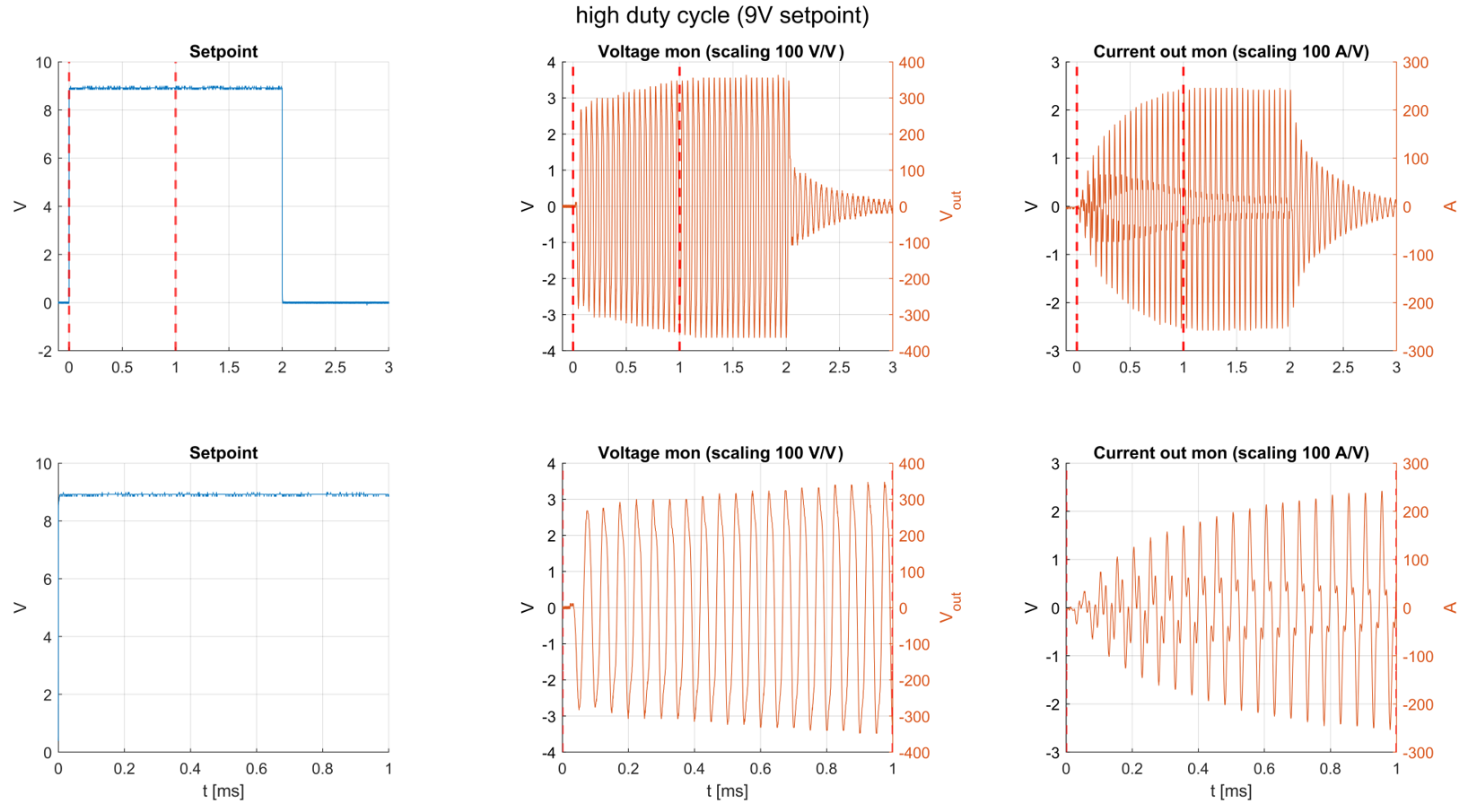
Figure 2: Input trigger (left),
output voltage (middle), output current (right). The bottom row shows a zoomed
in version of the red-banded section in the top row.
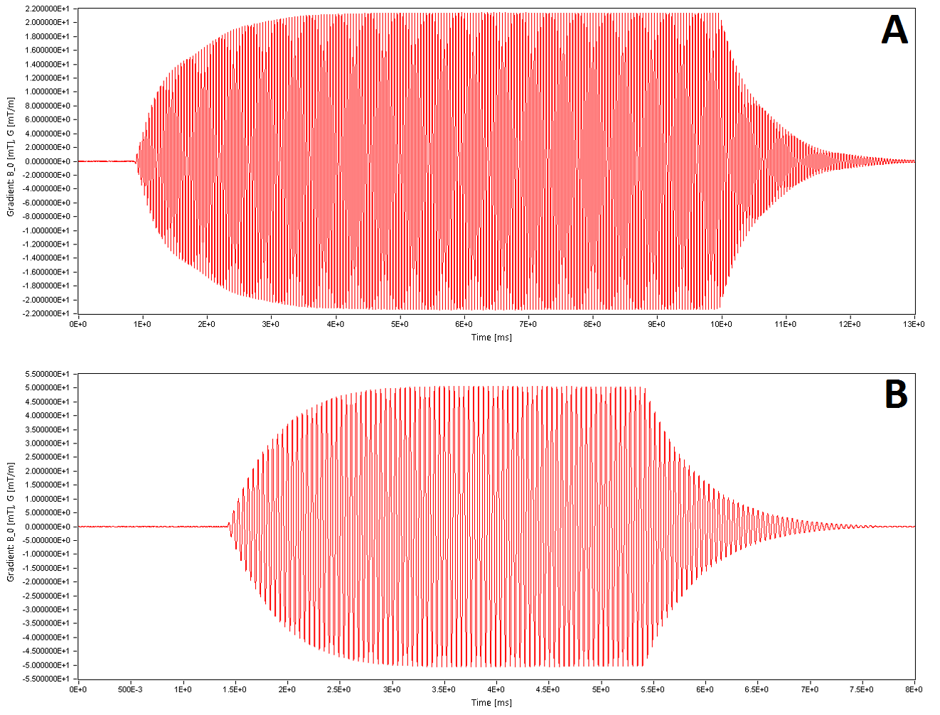
Figure 3: Comparison of the field
generated by the audio amplifier (A) and gradient amplifier (B).
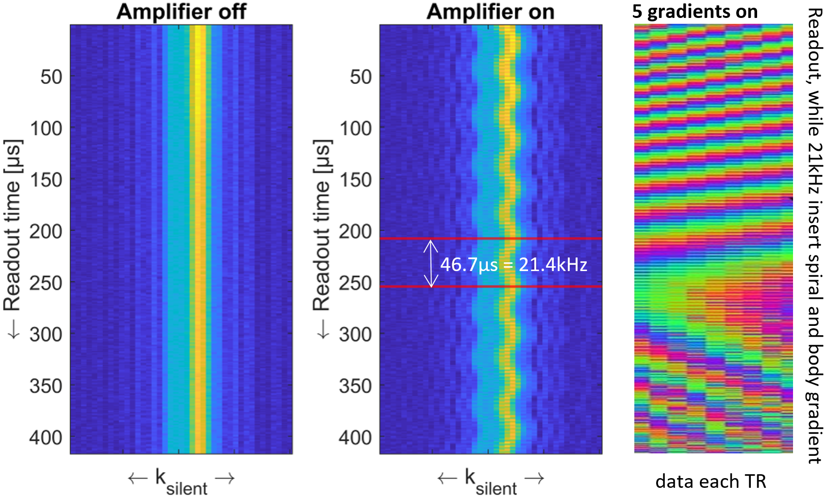
Figure 4: Effect of the oscillating
gradient on the MR-signal. Left: the MR-signal with the amplifier off. Middle:
the amplifier on. This data was acquired with a slice-selective 1D acquisition showing
only one of the simultaneously acquired 72 channels. Right: raw data
controlling all 5 gradients.