0562
Design and Development of a Next-Generation 7T human brain scanner with high-performance gradient coil and dense RF arrays.1Helen Wills Neuroscience Institute, University of California, Berkeley, CA, United States, 2Advanced MRI Technologies, Sebastopol, CA, United States, 3Department of Cognitive Neuroscience, Maastricht University, Maastricht, Netherlands, 4Siemens Healthcare GmbH, Erlangen, Germany, 5Department of Electrical Engineering and Computer Sciences, University of California, Berkeley, CA, United States, 6Radiological Sciences Laboratory, Stanford University, Stanford, CA, United States, 7Radiology, University of California, San Francisco, CA, United States, 8San Francisco Veteran Affairs Health Care System, San Francisco, CA, United States, 9A.A. Martinos Center for Biomedical Imaging, Dept. of Radiology, Massachusetts General Hospital, Charlestown, MA, United States, 10Harvard Medical School, Boston, MA, United States, 11Harvard-MIT Division of Health Sciences Technology, Cambridge, MA, United States, 12Siemens Medical Solutions USA, Inc, Cary, NC, United States, 13Computer Assisted Clinical Medicine, Medical Faculty Mannheim, Heidelberg University, Heidelberg, Germany
Synopsis
A Next-Generation 7T MRI scanner was designed to achieve higher performance in human brain imaging for the NIH BRAIN Initiative. The new 7T scanner introduces several innovative hardware designs including a PNS optimized asymmetric head gradient coil (Siemens Healthcare, Erlangen, Germany) with Gmax 200mT/m and Smax 900T/m/s. The scanner also includes 128-channel RF receiver and 16-channel transmit systems for all-in-one cumulative gains in performance. The resulting higher spatial resolution, sensitivity and image acceleration will enable in-vivo whole-brain mesoscale research on cortical layer and columnar circuitry and other brain structures.
Purpose
An MRI scanner specifically designed for brain imaging1,2 can have considerable advantage over whole body scanners by avoiding PNS and adhering to cardiac safety limits to reach higher gradient slew rate for EPI based neuroimaging3-5. This BRAIN Initiative project (U01EB025162) has developed a Next-Generation 7T brain scanner including novel head gradient coil (GC) and high channel count receiver and transmit capabilities integrated into a MAGNETOM Terra system (Siemens Healthcare, Erlangen, Germany). The main focus of the gradient development is to incorporate several innovative designs that provide additional degrees of freedom, enabling performance breakthroughs. Here we report on this new technology and works-in-progress scanner development.Methods
Design goals of RF receiver:A 128-channel (ch) receiver system is needed to support high-density coil arrays with small loop diameter (30mm-50mm) covering the head. Closely fitted arrays can increase the SNR in brain regions close to the loops, primarily neocortex. Furthermore, the higher spatial sensitivity in denser arrays reduce g-factor in acceleration techniques (SMS, parallel imaging) for higher accelerations. Shielding of receive and transmit cables in the energy chain is needed to avoid vibrations and potential breaking of wire connections.
Design goals of Gradient system:
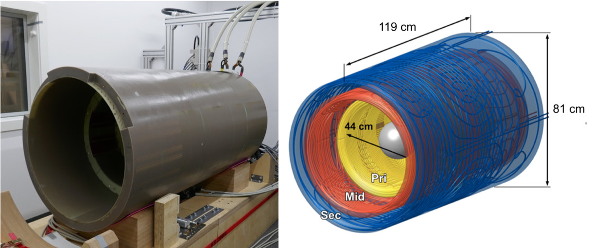
A gradient power amplifier (GPA) with high current output enables a larger (440-mm inner diameter) bore gradient coil for human subject access and for neuroscience research. Direct cooling of the conductor enables higher current density to achieve higher gradient performance. A third intermediate winding layer provides additional degrees of freedom for minimizing PNS6-8 for higher slew rates, minimization of the stray field. The 3-step asymmetric geometry also gives new degrees of freedom to tune mechanical dynamics to minimize vibrations and acoustics.
Results
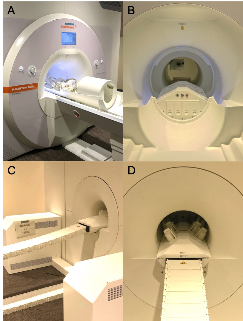
The new research scanner is currently being integrated at the UC Berkeley Neuroscience Institute.Receiver: The system includes a fully integrated 128-channel receiver system. An RF coil with up to 128 receive elements and onboard preamps can be plugged into the patient table. There are clinical style sockets, each with up to 32 receive coax and 32 DC lines that provide PIN diode control signals for detuning receive elements.
Transmitter: The Tx system has 16x 2kW peak RF power with independent RF pulse waveform generators for full dynamic parallel transmit (pTx) experiments. The system assures safe scanning by monitoring global and local SAR, using Virtual Observation Point models (VOP).
Gradients: Geometry: The 440mm gradient inner diameter (Figure 1) enables efficient acoustic system optimization and space for larger RF coils. The 3-step front coil design contiguous with the 600mm diameter magnet bore allows unrestricted patient access with shoulder space in coil and reduces claustrophobic feelings. Gradient Performance: Using a 1200A, 2250V GPA, the Gmax achievable is 200mT/m. The PNS-optimized4-6 gradient conductor and geometric design raised stimulation threshold limits to allow PNS-free operation in a large portion of the 200 mT/m - 900 T/m/s parameter space with no risk of cardiac stimulation. Non linearity: maximum field linearity deviation at worst case location in a 200mm sphere in % are X:6.9, Y:7.0 and Z:9.0. Gradient-magnet interactions are negligible due to extremely low GC stray fields. Intrinsically balanced forces and torques are achieved, Max. torque @ 1200A @ 7T in Nm is (X:28, Y:150, Z:0). Dynamics: The GC has low mechanical vibration due to high mass of GC (1060kg) and several incorporated stiffening cylinders and potting manufacturing process. Acoustics: the weight and stiffness make for a relatively quiet gradient coil, below 130dB(A). Vibrations in the frequency range less than 100Hz are very small due to force and torque compensations optimized by 3 stepped layer design. Both low amplitude and numbers of critical frequency bands were achieved by making different resonance peaks coincident, with none between 600Hz and 1200Hz or in extremely high frequencies. Cooling: The GC is equipped with more than 50 temperature sensors. Large wire cross sections and short cooling loop lengths enable low gradient-coil temperatures. Maximum temperature measured on hot spot inside GC increased to 31.7oC from 20.5oC @150% duty cycle, 80mT/m for 30 minutes. Active E-shims included 1st and 2nd order harmonics. This extremely high slew rate required a thin copper RF shield to minimize its eddy currents.
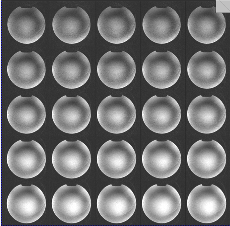
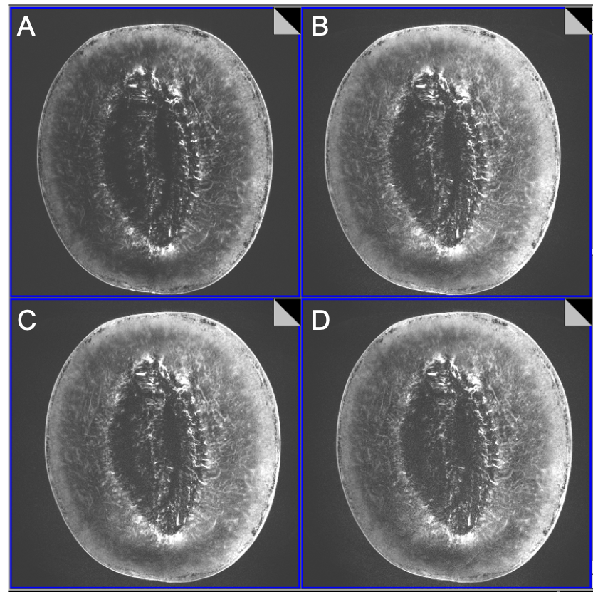
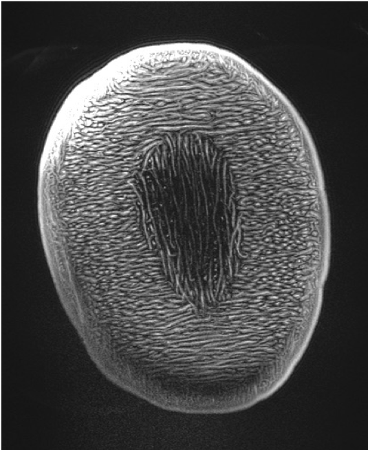
Imaging Experiments: Initial imaging began 2 days before submission of this abstract. Human imaging is temporarily restricted pending safety testing. A novel high density array Rx/96-ch,Tx/16-ch coil was used9. Figure 3 shows initial imaging using GE-EPI of phantom. Figure 4 shows FLASH images of melon at different accelerations up to 18 and Figure 5 shows image of squash at acceleration 15, possible with the 96-ch array.
Conclusions
Development of the "Impulse" gradient and integration of the 128-channel receiver into the MAGNETOM Terra scanner was achieved by Siemens Healthcare in collaboration with Harvard MGH and UC Berkeley. The Impulse asymmetric gradient coil has a novel 3-layer design for additional degrees of freedom to simultaneously improve slew rate, stray field and mechanical dynamics, and minimize PNS altogether. The 128-channel receiver system enables use of high-density receiver arrays for greater sensitivity and higher accelerations. The scanner's initial performance is very promising for imminent improvements in brain imaging. Cumulative gains from gradient, receiver and imaging sequence improvements should enable robust imaging of mesoscale neurocircuitry and brain structure.Acknowledgements
Research reported in this publication was supported by the National Institute of Biomedical Imaging and Bioengineering, and the National Institute for Mental Health of the National Institutes of Health and the BRAIN Initiative under award numbers U01EB025162, 1R01MH111444, and Weill NeuroHub. The content is solely the responsibility of the authors and does not necessarily represent the official views of the National Institutes of Health.References
[1] Weiger et al., “A high-performance gradient insert for rapid and short-T2 imaging at full duty cycle,” Magn Reson Med, vol. 79, no. 6, pp. 3256–3266, 2018.
[2] Tan et al., “Peripheral nerve stimulation limits of a high amplitude and slew rate magnetic field gradient coil for neuroimaging,” Magn Reson Med, vol. 83, no. 1, pp. 352–366, 2020.
[3] Setsompop et al., “Pushing the limits of in vivo diffusion MRI for the human connectome project,” NeuroImage, vol. 80, pp. 220 – 233, 2013
[4] McNab et al., “The human connectome project and beyond: Initial applications of 300 mT/m gradients,” NeuroImage, vol. 80, pp. 234 – 245, 2013
[5] Feinberg et al., “Pushing the limits of ultra-high resolution human brain imaging with SMS-EPI demonstrated for columnar level fMRI,“ NeuroImage. vol. 164, pp155-163, 2018
[6] Davids et al. "Prediction of peripheral nerve stimulation thresholds of MRI gradient coils using coupled electromagnetic and neurodynamic simulations." Magnetic resonance in medicine 81.1 (2019): 686-701.
[7] Davids et al. “Optimizing selective stimulation of peripheral nerves with arrays of coils or surface electrodes using a linear peripheral nerve stimulation metric,” J Neural Eng, vol. 17, no. 1, p. 016029, 2020
[8] Davids et al. PNS optimization of a high-performance asymmetric gradient coil for head imaging. ISMRM, 2021.
[9] Gunamony et al. A 16-channel transmit 96-channel receive head coil for NexGen 7T scanner. ISMRM, 2021.
Figures