0561
Design and Construction of a Low-Cryogen, Lightweight, High-Performance, Head-only Compact 7T MRI
Thomas K.F. Foo1, Mark Vermilyea2, Minfeng Xu2, Anbo Wu2, Yihe Hua2, Wolfgang Stautner2, Ye Bai2, Justin Ricci2, Doug Kelley3, John III Huston4, Yunhong Shu4, Matt A Bernstein4, Christopher Hess5, and Duan Xu5
1GE Global Research, Niskayuna, NY, United States, 2GE Research, Niskayuna, NY, United States, 3GE Healthcare, Fairfax, CA, United States, 4Mayo Clinic, Rochester, MN, United States, 5University of California - San Francisco, San Francisco, CA, United States
1GE Global Research, Niskayuna, NY, United States, 2GE Research, Niskayuna, NY, United States, 3GE Healthcare, Fairfax, CA, United States, 4Mayo Clinic, Rochester, MN, United States, 5University of California - San Francisco, San Francisco, CA, United States
Synopsis
A design for a lightweight, low-cryogen, head-only 7T MRI system was completed with its construction underway. This new 7T system is a dedicated brain scanner with 140 mT/m and 820 T/m/s gradients and weighs about 8 tons with 18 liters of liquid helium. The fringe field is similar to the 5 Gauss limits of a clinical whole-body 3T MRI scanner.
Introduction
Previous work demonstrated that a compact, lightweight, low-cryogen head-only 3T MRI system can be built using thermosiphon technology and asymmetric gradients [1]. That 3T system, operational since 2016, demonstrated the value of high slew rate gradients with negligible peripheral nerve stimulation (PNS) to reduce spatial distortion in EPI [2] and non-cartesian imaging [3,4] of the brain. One of the strongest appeals of a compact, low-cryogen system is in the ease of installation where cryogen venting is not needed, and requiring a much smaller space. The overall high cost of whole-body 7T systems and its installation, in which extensive magnetic shielding and siting costs exceed the systems cost itself, impedes access to ultra-high field brain imaging.Our goal is to leverage the technology demonstrated in the Compact 3T MRI (C3T) to design and build a high-performance, head-only 7T MRI scanner that can provide improved imaging capability as well as a substantial reduction in installation effort and cost in comparison to existing 7T MRI . Our design targets were: magnet weight and 5G fringe field approximately that of a whole-body 3T, and little or no helium. The proposed Compact 7T system can be installed in locations that accommodate a whole-body 3T clinical scanner but also not require any cryogen venting. In addition, a custom head gradient specified 2x the gradient amplitude and 4x the slew rate of whole-body 7T MRI systems.
Methods
Table 1 lists the design specifications of the proposed Compact 7T (C7T). Initial gradient specifications are also listed, leveraging our gradient design experience for the C3T [1] and MAGNUS [5] gradient coils. As a head-only system, the gradient coil design called for a symmetric z-coil and asymmetric transverse (x- and y-axis) coils. Established and proven superconducting wire technology using copper-clad NbTi wire was used in the design. To substantially reduce the weight of the C7T magnet, the magnet design focused on eliminating the solenoidal coil that is used in conventional 7T magnet design. This design consideration puts an emphasis on managing and controlling the large axial forces between the main magnet coils, without resorting to large and heavy coil support structures.Results
Magnet designAs shown in Table 1, the final design for the C7T magnet was a conventional 6-main coil and 2-bucking coil design (Figure 1), without a solenoidal coil. This allowed the magnet weight and size to be substantially reduced, achieving an 8-ton magnet weight. As the superconductor mass of the C7T was about 10x that of the C3T magnet with 86 km of NbTi wire, 3 Sumitomo RDE-412x4 cold-heads provide the required 2nd stage cooling power of 1.25 W at 3.4 K for each unit. This compares to the 2 cold-heads in a whole-body 7T magnet. As such, a liquid helium volume of 18 liters was achieved compared to 12 liters in C3T. The design simulations indicated that this configuration allows the C7T magnet to be ramped in 9 hours to 450 A (Figure 2).
Gradient design
As the magnet warm bore diameter was identical to that of C3T, the C7T gradient coil was similar but was slightly more efficient. The C7T gradient coil was designed to minimize magnet-gradient interaction, which is critical for a non-liquid bath magnet. With a 900 A gradient driver, the C7T gradient coil design achieves an efficiency of 0.16 mT/m/A, compared 0.13 mT/m/A in the C3T gradient, and 0.33 mT/m/A in the MAGNUS gradient coil. A single-layer primary and shield coil design was used due to the need to fit the gradient coil in the 62-diameter magnet warm bore. This design allowed a 95% of the population to fit into the magnet and gradient isocenter, as shown in Figure 3.
With the 140 mT/m gradient amplitude and 820 T/m/s slew rate achieved with this gradient design, comparable ~2x reduction in EPI echo spacing and geometric distortion as with C3T (80 mT/m and 700 T/m/s) and MAGNUS (200 mT/m and 500 T/m/s) systems is anticipated [2]. Although the C7T maximum gradient amplitude is less than that of MAGNUS, similar reduction in diffusion TE times is achieved (Figure 4). Compared to existing whole-body 7T systems, the C7T MRI system will achieve about a 2x reduction in diffusion TE times, and a 20% reduction in diffusion pulse widths. This represents diffusion encoding closer to the small pulse width approximation at high b-values and also an SNR advantage of >1.8 compared to whole-body 7T. In addition, as the C7T gradient has about the same form factor as the C3T and MAGNUS gradients, PNS thresholds should be also comparable, with negligible PNS noted compared to whole-body 7T.
Discussion
Our C7T design achieves the goal of having a magnet of similar weight and size of a whole-body 3T magnet. This suggests that C7T can be installed in the same space as a clinical 3T MRI without additional structural reinforcement. As such, C7T could be a simple replacement for existing clinical 3T MRI scanners, providing greater access to ultra-high field brain imaging. Furthermore, the high-performance C7T gradients enable new microstructure imaging methods, such as slow flow imaging [6] and time-dependent diffusivity using oscillating gradient spin echoes [7], to be used at 7T.Acknowledgements
Grant funding: NIH U01EB026976.References
1. Foo TKF, et al. Magn Reson Med 2018; 80: 2232–45.
2. Tan ET, et al. J Magn Reson Imag 2016; 44: 653-64.
3. Kang D, et al. Magn Reson Med 2020; 84: 192-205.
4. In MH, et al. Phys Med Biol 2020; 65: 15NT02.
5. Foo TKF, et al. Magn Reson Med 2020; 83: 2356–69.
6. Jansen-Heukensfeldt I, et al. ISMRM 2020; 972.
7. Tan ET, et al. Magn Reson Med 2020; 84: 950-65.
Figures
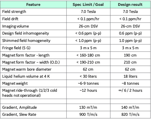
Table 1: Initial target system specifications and the resulting C7T
design results for the magnet and gradient coil.
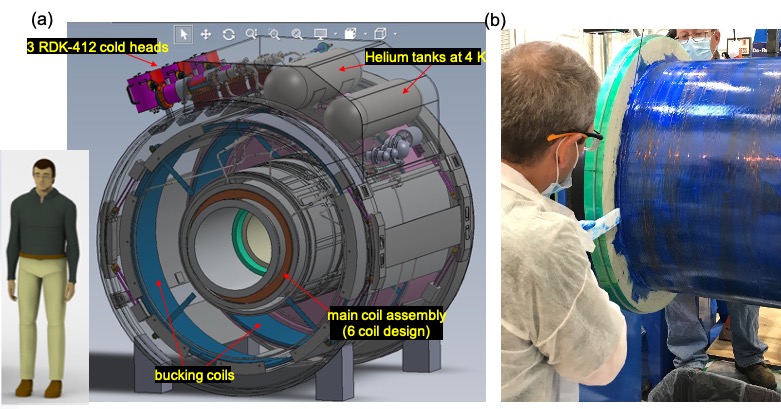
Figure 1: (a)
Proposed C7T magnet showing the 8-coil configuration, cold heads, and helium
tanks. The size of the C7T relative to an average person is also shown for
scale. (b) One of the 2 large main coils being wound with superconducting NbTi
wire.
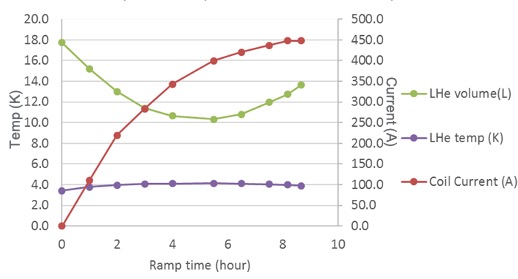
Figure 2:
Simulation of the magnet heat load during the ramp process showing that the
target current of 450 A can be achieved within 9 hours. The change in liquid
helium volume and temperature is also shown as the magnet is ramped.
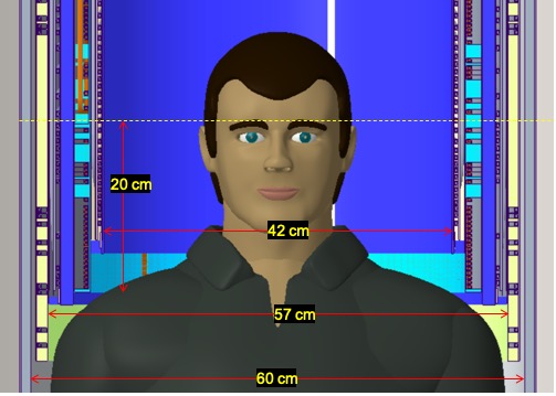
Figure 3: C7T
asymmetric (transverse) gradient design showing the stepped gradient coil and
patient access relative to a 95% man. The patient bore dimensions are slightly
larger than that for the C3T.
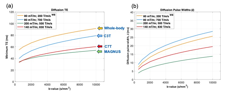
Figure 4: Diffusion
imaging performance at different b-values showing (a) diffusion TE time, and
(b) diffusion pulse width (d) for gradient configurations of whole-body
7T, C3T, C7T, and MAGNUS. The
performance improvement between the C7T gradient and the whole-body 7T is
clear.