0559
A portable brain MRI scanner based on a 72 mT, 35 kg "Halbach-bulb" magnet and external gradient coil1Athinoula A. Martinos Center for Biomedical Imaging, Massachusetts General Hospital, Charlestown, MA, United States, 2Harvard Medical School, Boston, MA, United States, 3Harvard–MIT Division of Health Sciences and Technology, Cambridge, MA, United States
Synopsis
There is clear motivation for increasing the accessibility of MRI, particularly for brain imaging. To address this, we present a portable tight-fitting MRI scanner with a geometry that is optimized for head. We use a 35kg “Halbach-bulb” permanent magnet design that combines a Halbach sphere and Halbach cylinder. The gradient coils are designed on the outer surface of the magnet, enabling a closer-fit B0 magnet. The inhomogeneous B0 magnet results image distortion, which we correct using a generalized reconstruction algorithm that employs measured field maps. We present the full scanner system and in vivo 3D images with resolution 1.5mmx2.7mmx7mm.
Introduction
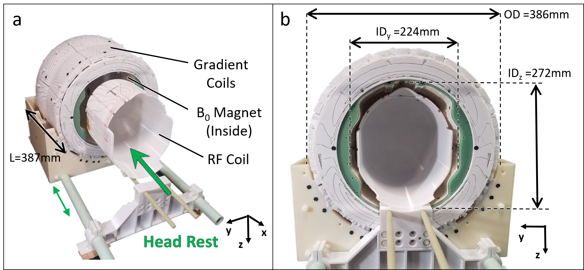
Access to MRI is limited by cost, size, and siting requirements. Specialized portable systems could increase accessibility and enable point-of-care (POC) MRI [1]–[6]. We developed a head-only, portable, low-field MRI scanner based on a Halbach-bulb permanent magnet design and external gradient coils. The system (magnet, gradients, shims, RF) weighs 50 kg with outer dimension 39cmx39 cm (Figure 1). Here we present the overall design and in vivo brain imaging validation.Methods
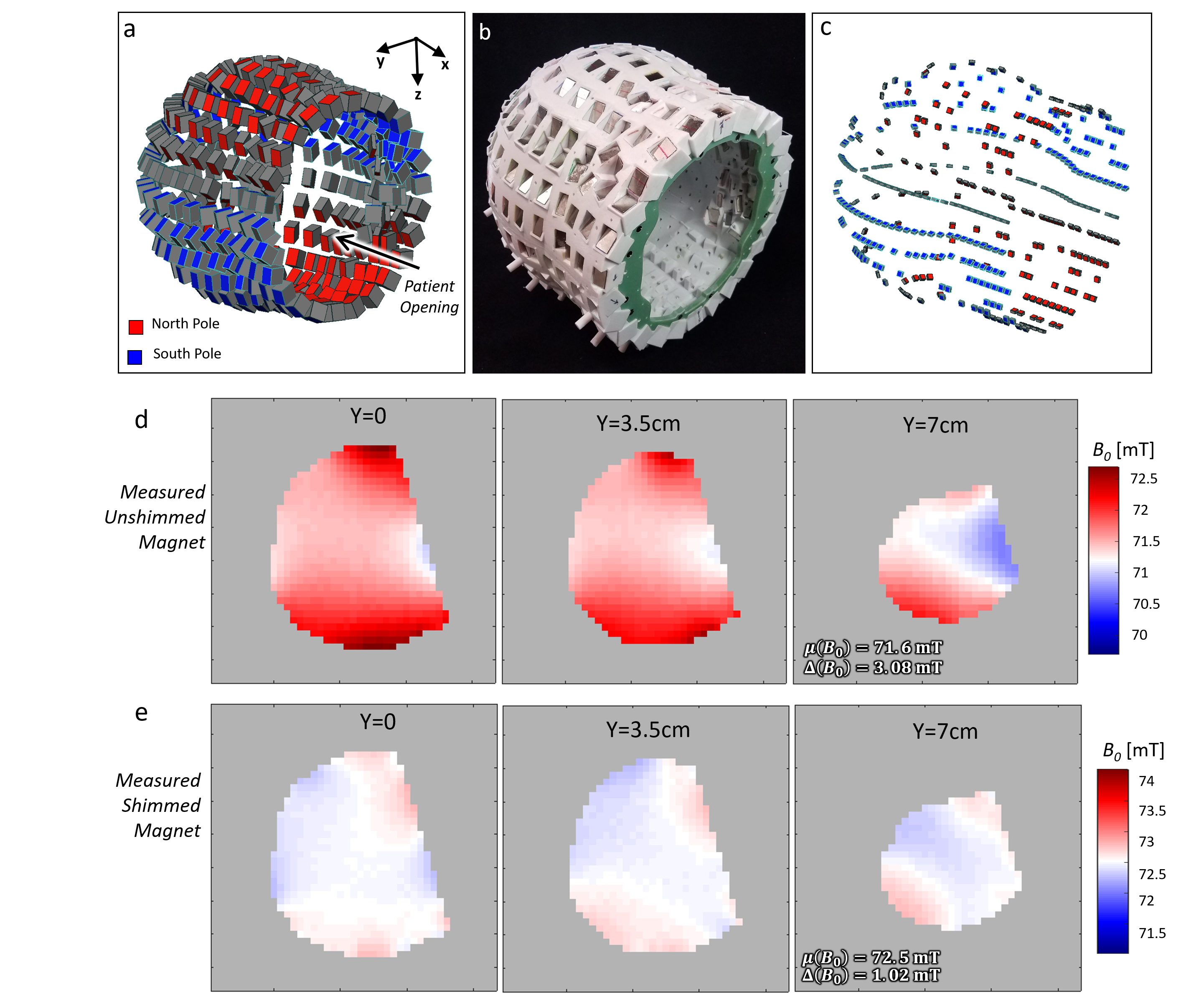
The scanner was optimized for whole-brain human imaging in adults. Figure 1 shows the magnet, gradient and RF coil components (without patient table). From the patient outward, the components are: RF Tx/Rx coil, B0 shim magnets, RF shield, main B0 magnet, and x, y, and z gradient coils. During the scan, the patient’s head rest on the RF coil. The rest of the system ( B0 magnet, RF shield, and gradient coils) is on rails and slides over the coil and patient.The scanner employs a sparse array of NdFeB permanent magnets in a “Halbach bulb” configuration [7], a design that merges a Halbach cylinder and Halbach sphere. Compared to a dipole magnet or Halbach cylinder, the design conforms around the head and yields a more efficient field-to-weight ratio. The target field optimization allowed for 326 NdFeB blocks to vary in size and angular position using a min-max field homogeneity cost function and constraint of B0 > 70mT [7]. The magnet former was 3D-printed in 4 quadrants with PC-10 polycarbonate material and constructed with reinforcement elements (including a fiberglass front ring) as shown in Figure 2b. The measured B0 map had a mean of 71.6 mT and ROI range of 3.08 mT. The placement of small shim magnets was then optimized to improve ROI range 1.02mT. Figure 2 shows the measured unshimmed and shimmed field maps. The constructed magnet weight is 35 kg.
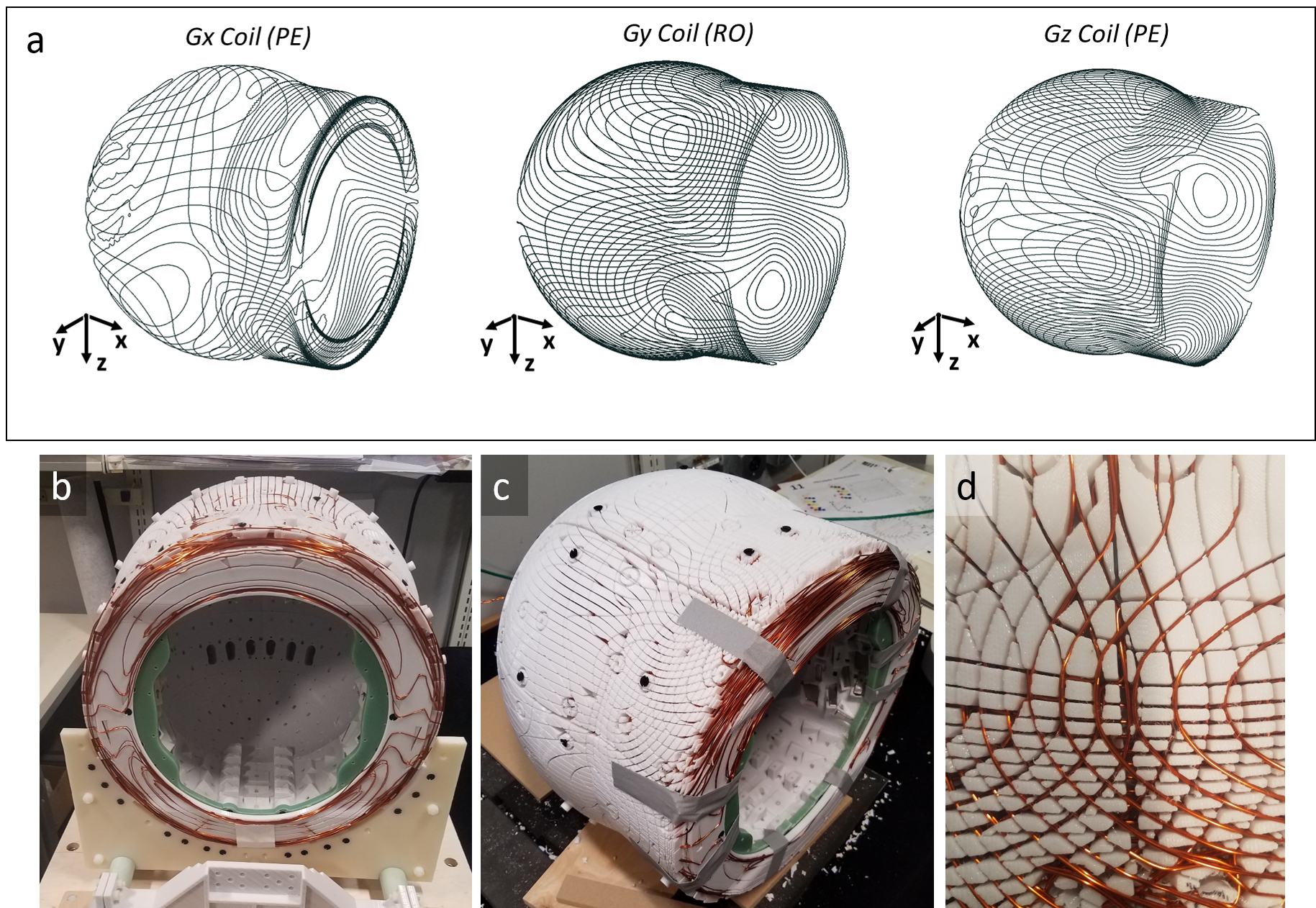
The three gradient coils are designed on the outer surface of the magnet (Figure 3) to minimize the diameter of the magnet to thus maximize field strength. Unworkable in many magnets, this placement is possible because of the minimal eddy current effects in the NdFeB magnets. The AWG18 wire gradient coils are ordered: (from in to out) x-y-z. The design surface for the y and z coils was the outer cylindrical+spherical surface of the B0 magnet; the design surface for the x coil used same surface, plus an additional annulus on the patient-side face of the magnet. We target-field optimize the current paths using a stream function BEM solver based on a published toolbox [8], [9] resulting Gx, Gy, and Gz coils with efficiencies of 0.275mT/mA, 0.939mT/mA, and 1.078mT/mA respectively.
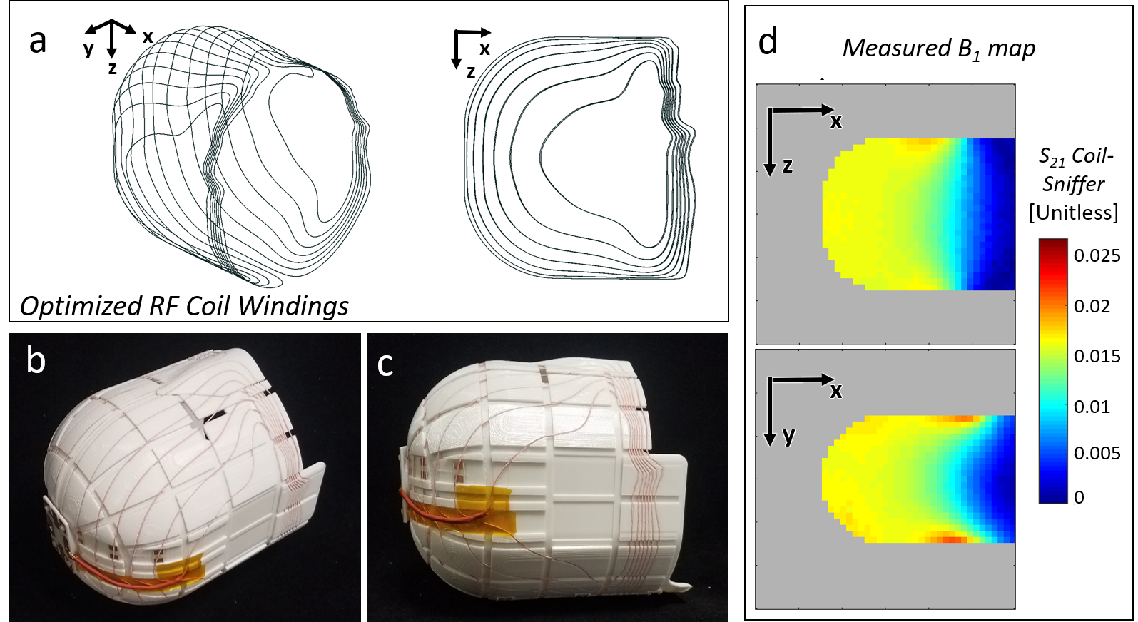
The transverse RF Tx/Rx coil (Fig. 4) was also target-field optimized. The transverse field was designed to minimize Tx and Rx in the un-encoded lower part of the head/neck, to prevent undesirable signal pick-up that aliases back into the FOV. The BEM stream-function sought a homogeneous target field in the ROI and a target field of zero in the lower head/neck area. Figure 4c shows the resulting B1 map (measured using an S12 map with a pickup coil).
A 50hm, 37db gain pre-amp (MITEQ model AU-1583) and second stage 24db gain amplifier (Minicircuits ZFL-500LN+) were used prior to the Tecmag Bluestone console. Other components include: AE Techron 7224 and 7548 gradient amplifiers for phase encoding and readout respectively and a 2kW RFamp (Tomco BT02000-AlphaS-3MHz).
A T2-weighted (TEeff = 134ms) was acquired in a healthy subject using a 3D RARE sequence and frequency swept RF pulses (50 KHz sweep). To correct for encoding and B0 field imperfections, we apply a model-based generalized image reconstruction technique using measured field maps.
Results
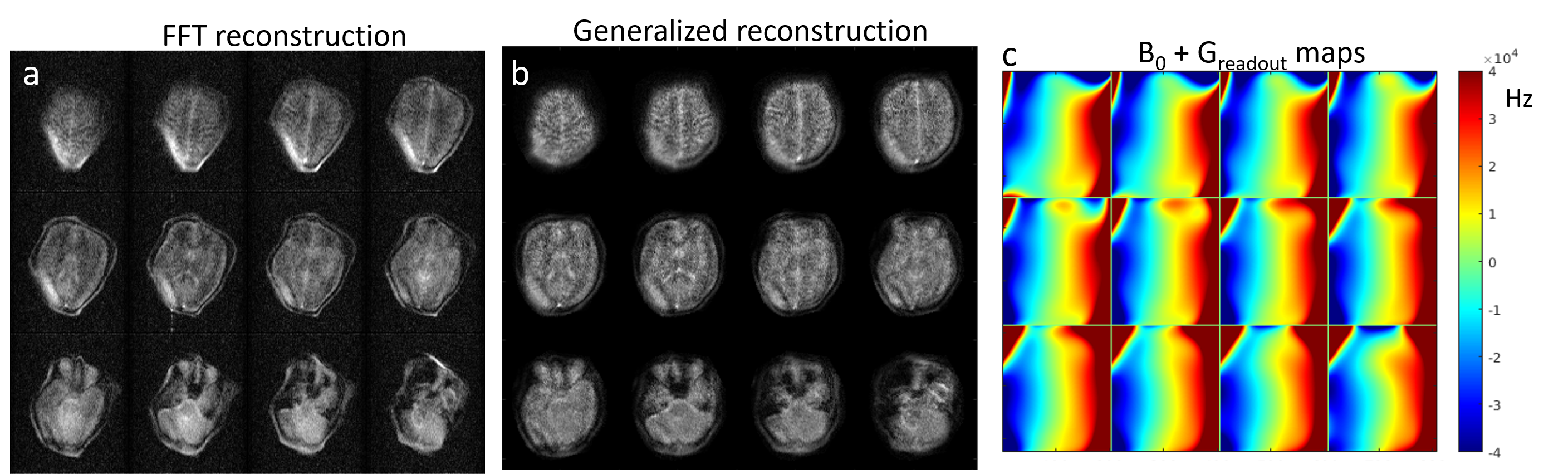
Preliminary images from healthy subjects acquired in a shielded environment are shown in Figure 5. The images have 1.5 x 2.7 mm in-plane resolution and 7mm thick partitions. The 3D image was acquired in 25 minutes with 6 averages to improve SNR. Figure 5a shows a reconstructed image assuming all linear encoding fields and the same data using the generalized encoding model reconstruction (5b). Figure 5c shows the field maps that were employed in the encoding model to reconstruct the images in Fig. 5b. These field maps are the combination of the measured B0 field variation and the measured readout (Gy) gradient field maps.Discussion
Although, most of the image distortion is corrected in Fig. 5b, a bright area remains in the lower left region of the images from signal pile-up in a poorly encoded area in the FOV. A 2nd round of magnet shimming may improve this area. Alternatively, an image with a reversed readout polarity can be acquired, which results in a different distortion pattern which could be combined to eliminate problematic encoding locations. These images were acquired in a shielded room. Work is ongoing in suppressing electromagnetic interference (EMI) using external detectors [11], to allow use at the point-of-care.Conclusion
We present a new very compact, lightweight portable MRI scanner design for POC operation with in vivo brain imaging. Such a lightweight portable system could extend the reach of MRI into unconventional locations, such as ERs, ICUs, neonatal ICUs, and rural clinics.Acknowledgements
We openly acknowledge that the scanner design and construction was completed by Patrick C. McDaniel as part of his PhD thesis. We thank Stephen Cauley, Martin Hurlimann, Bastien Guerin, Monika Śliwiak, Sai Abitha Srinivas for their help with the imaging experiments. Funding from NIH NIBIB R01EB018976.References
[1] Cooley CZ, McDaniel PC, Stockmann JP, Srinivas SA, Cauley SF, Śliwiak M, Sappo CR, Vaughn CF, Guerin B, Rosen MS, Lev MH, Wald LL. A portable scanner for magnetic resonance imaging of the brain. Nat Biomed Eng. 2020. Epub ahead of print. PMID: 33230306.
[2] L. L. Wald, P. C. McDaniel, T. Witzel, J. P. Stockmann, and C. Z. Cooley, “Low-cost and portable MRI,” J. Magn. Reson. Imaging, vol. n/a, no. n/a, Jan. 2020, doi: 10.1002/jmri.26942.
[3] O'Reilly T, Teeuwisse WM, de Gans D, Koolstra K, Webb AG. In vivo 3D brain and extremity MRI at 50 mT using a permanent magnet Halbach array. Magn Reson Med. 2021 Jan;85(1):495-505. doi: 10.1002/mrm.28396. Epub 2020 Jul 5. PMID: 32627235; PMCID: PMC7689769.
[4] T. K. F. Foo et al., “Lightweight, compact, and high-performance 3T MR system for imaging the brain and extremities,” Magn. Reson. Med., vol. 80, no. 5, pp. 2232–2245, Dec. 2018, doi: 10.1002/mrm.27175.
[5] “Portable MRI – Hyperfine.” Dec. 13, 2019, [Online]. Available: https://www.hyperfine.io/portable-mri.
[6] Z. H. Ren, W. C. Mu, and S. Y. Huang, “Design and Optimization of a Ring-Pair Permanent Magnet Array for Head Imaging in a Low-Field Portable MRI System,” IEEE Trans. Magn., vol. 55, no. 1, pp. 1–8, 2019, doi: 10.1109/TMAG.2018.2876679.
[7] P. McDaniel, C. Z. Cooley, J. P. Stockmann, and L. L. Wald, “Numerically optimized design for a low-cost, lightweight 86mT whole-brain magnet,” Proc. 27th Annu. Meet. ISMRM, Montr. 2019, p. 1466, 2019.
[8] G. Bringout, K. Gräfe, and T. M. Buzug, “Performance of Shielded Electromagnet-Evaluation Under Low-Frequency Excitation,” IEEE Trans. Magn., vol. 51, no. 2, pp. 1–4, 2015, doi: 10.1109/TMAG.2014.2329396.
[9] J. P. Stockmann, C. Z. Cooley, B. Guerin, M. S. Rosen, and L. L. Wald, “Transmit Array Spatial Encoding (TRASE) using broadband WURST pulses for RF spatial encoding in inhomogeneous B<inf>0</inf> fields,” J. Magn. Reson., vol. 268, 2016, doi: 10.1016/j.jmr.2016.04.005.
[10] C. Z. Cooley, P. C. McDaniel, J. P. Stockmann, S. A. Srinivas, and L. L. Wald, “A Point-of-Care MRI Scanner for Human Brain Imaging,” Proc. 28th Annu. Meet. ISMRM, Paris, 2020, 2020.
[11] S. A. Srinivas, C. Z. Cooley, J. P. Stockmann, P. C. McDaniel, and L. L. Wald, “Retrospective Electromagnetic Interference Mitigation in a Portable Low Field MRI System,” Proc. 28th Annu. Meet. ISMRM, Paris, 2020, 2020.
Figures